EasyManuals Logo

Honeywell XNX Technical Manual

Honeywell XNX
200 pages
To Next Page IconTo Next Page
To Previous Page IconTo Previous Page
Page #70 background imageLoading...
Page #70 background image
XNX Universal Transmitter
Section 2 - Installation and Operation
68
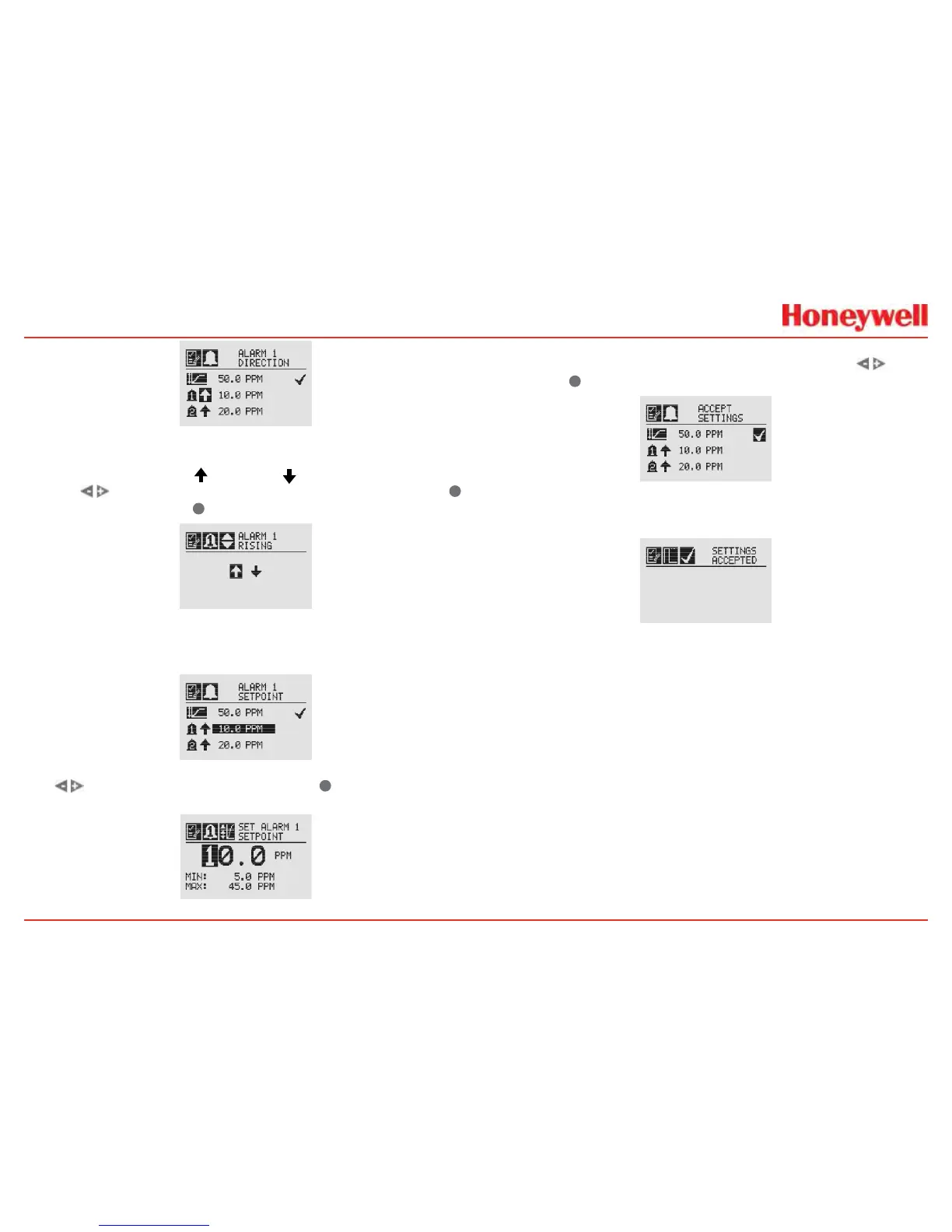
Figure 87. Alarm Direction
Theiconsnexttothebellimagesindicatewhetherthealarmhas
beentriggeredbyrising(
)orfalling( )gasconcentrations�
Usethe
switchestohighlighttheappropriatetrigger�Use
tomaketheselectionor
todiscardit�
Figure 88. Setting Alarm Rising/Falling
TheAlarmLimitsselectionsetsthealarmtriggerlevelforboth
alarms�
Figure 89. Alarm Limits
Use tosetthedesiredalarmlimitand
selectit�Repeat
foreachalarm�
Figure 90. Setting an Alarm Setpoint
Whencomplete,thedisplaywillreturntothemainRange&
Alarmscreen�Whenallsettingshavebeenmade,use
to
movetothe
onthedisplaytoAcceptSettings�
Figure 91. Accept Settings
Whenthesettingshavebeensaved,thefollowingscreenwill
appearonthedisplay
Figure 92. Settings Accepted Screen
SeeSection6�1ProductSpecicationsforECcellinformation�

Table of Contents

Other manuals for Honeywell XNX

Questions and Answers:

Question and Answer IconNeed help?

Do you have a question about the Honeywell XNX and is the answer not in the manual?

Honeywell XNX Specifications

General IconGeneral
Ingress ProtectionIP66/67
Product TypeUniversal Transmitter
Enclosure RatingIP66/67
DisplayLCD
Communication ProtocolsHART, Modbus, Foundation Fieldbus
Power Supply24 VDC nominal, 18-32 VDC
Operating Temperature-40°C to +65°C (-40°F to +149°F)
MaterialAluminum or Stainless Steel
Gas TypesToxic, Oxygen, and Combustible gases
Output4-20 mA
Relays3 programmable relays
ApprovalsATEX, IECEx, UL, CSA
Sensor CompatibilityElectrochemical, catalytic, infrared, and other sensor types

Related product manuals