CONTROL PANEL ON HEAT GENERATOR
10 4 213 563 / 03
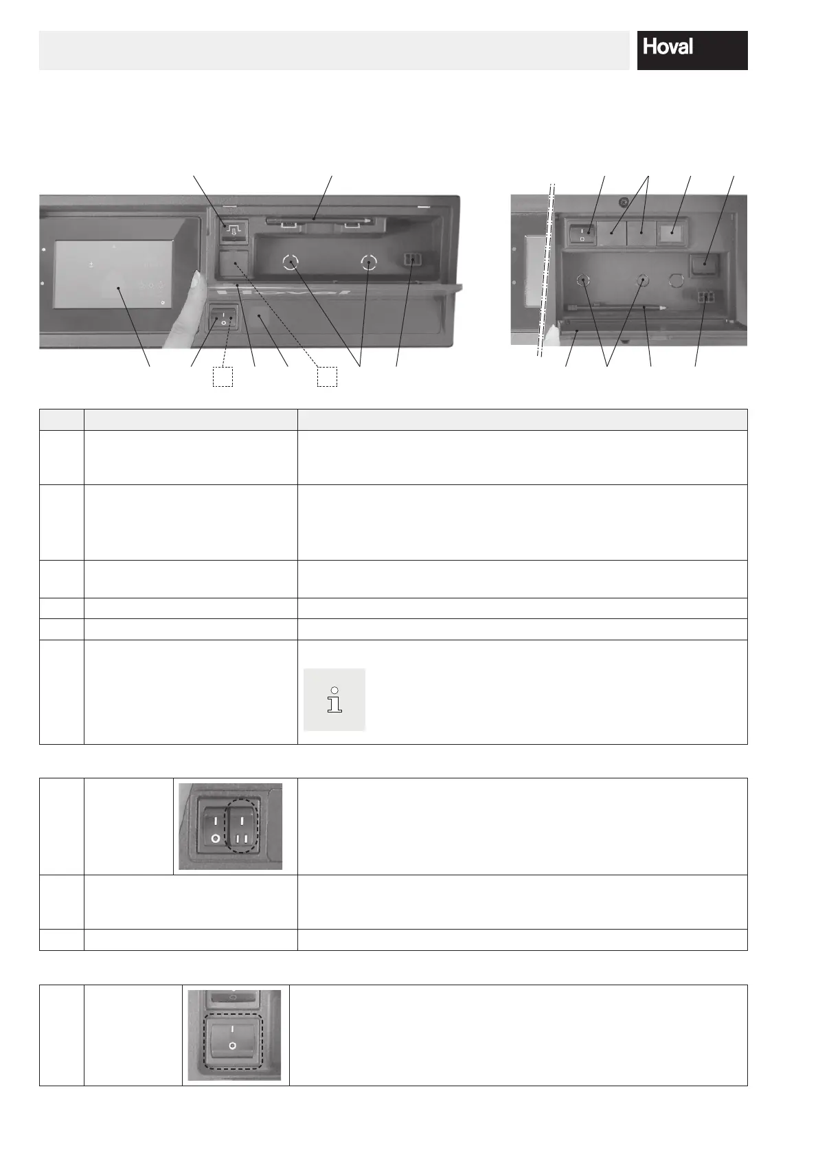
4. Control panel on heat generator
4.1 Overview of control panel
1 2
7
8
6
5 9 98
524
3
7
3 4
6
10
No. Designation Function
1 TopTronic
®
E control module Used as operator terminal for the plant that can be operated by touching
with the nger or stylus (no. 4). For a detailed description of the elements,
see chapter 5.6.1 page 17.
2 Blocking switch
1 = ON Heat generator in operation
0 = OFF Heat generator not in operation (plant live; no frost pro-
tection)
3 Flap To protect the folding compartment with stylus (no. 4), reset button (no. 6)
and service plug (no. 9). Safety temperature limiter optional (no. 8)
4 Stylus Stylus for operating the control module
5 Fault lamp Lights up if there is a heat generator fault.
6 Reset button Used for resetting if the failure indication lamp lights up.
The reset button is allowed to be pressed once at most. If
the
failure indication lamp continues to be lit, please contact
Hoval Customer Service.
Optional:
7 Bivalent
switch
(optional)
Used for switching priority in plants with several heat generators or for
other plant-specic switching functions.ww
8 Additional safety temperature
limiter
(optional)
Optional installation of an additional safety temperature limiter. Used for
interrupting the heat generator if a set temperature is exceeded.
9 Service plug Used exclusively by the service technician.
Only available for specic heat pumps:
10 Mains isola-
tor switch
Below the reset button, there is a mains isolator switch with which the heat
pump can be completely disconnected from the electrical power supply.