183
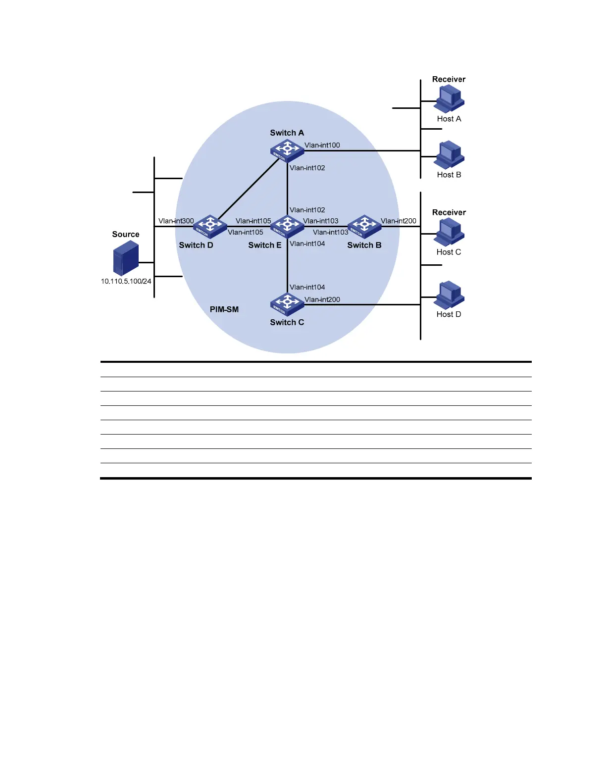
Figure 53 Network diagram for PIM-SSM configuration
Ethernet
EthernetEthernet
N1N2
Vl
an-i
n
t101
Vlan-int101
Device Interface IP address Device Interface IP address
Switch A Vlan-int100 10.110.1.1/24 Switch D Vlan-int300 10.110.5.1/24
Vlan-int101 192.168.1.1/24 Vlan-int101 192.168.1.2/24
Vlan-int102 192.168.9.1/24 Vlan-int105 192.168.4.2/24
Switch B Vlan-int200 10.110.2.1/24 Switch E Vlan-int104 192.168.3.2/24
Vlan-int103 192.168.2.1/24 Vlan-int103 192.168.2.2/24
Switch C Vlan-int200 10.110.2.2/24 Vlan-int102 192.168.9.2/24
Vlan-int104 192.168.3.1/24 Vlan-int105 192.168.4.1/24
Configuration procedure
1. Configure IP addresses and unicast routing.
Configure the IP address and subnet mask for each interface according to Figure 53 (details not shown).
Configure OSPF on the switches in the PIM-SM domain to ensure network-layer reachability among them
(details not shown).
2. Enable IP multicast routing, and enable PIM-SM and IGMP.
# Enable IP multicast routing on Switch A, enable PIM-SM on each interface, and run IGMPv3 on VLAN-
interface 100, which connects Switch A to the stub network.
<SwitchA> system-view
[SwitchA] multicast routing-enable
[SwitchA] interface vlan-interface 100
[SwitchA-Vlan-interface100] igmp enable
[SwitchA-Vlan-interface100] igmp version 3
[SwitchA-Vlan-interface100] pim sm
[SwitchA-Vlan-interface100] quit

 Loading...


