270
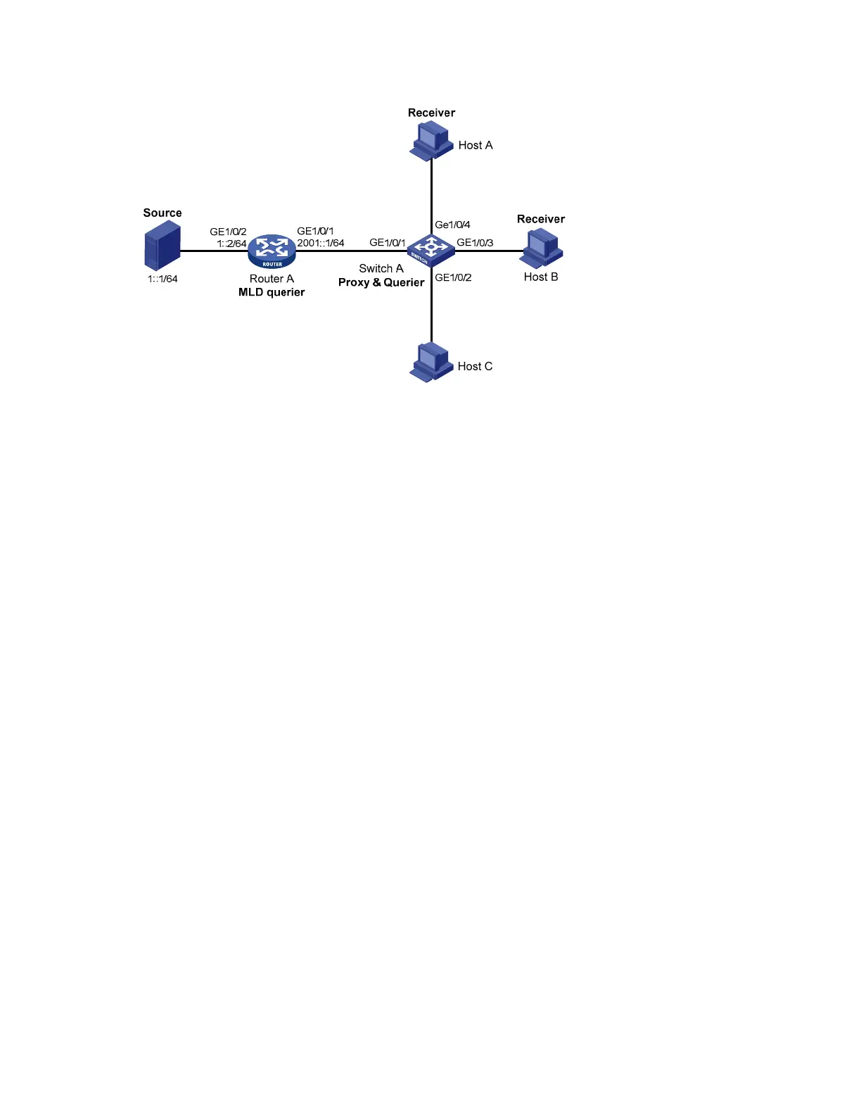
Figure 69 Network diagram for MLD snooping proxying configuration
Configuration procedure
1. Configure IPv6 addresses for interfaces
Configure an IP address and prefix length for each interface according to Figure 69 (details not shown).
2. Configure Router A
# Enable IPv6 multicast routing, enable IPv6 PIM-DM on each interface, and enable MLD on port
GigabitEthernet 1/0/1.
<RouterA> system-view
[RouterA] multicast ipv6 routing-enable
[RouterA] interface gigabitethernet 1/0/1
[RouterA-GigabitEthernet1/0/1] mld enable
[RouterA-GigabitEthernet1/0/1] pim ipv6 dm
[RouterA-GigabitEthernet1/0/1] quit
[RouterA] interface gigabitethernet 1/0/2
[RouterA-GigabitEthernet1/0/2] pim ipv6 dm
[RouterA-GigabitEthernet1/0/2] quit
3. Configure Switch A
# Enable MLD snooping globally.
<SwitchA> system-view
[SwitchA] mld-snooping
[SwitchA-mld-snooping] quit
# Create VLAN 100, assign ports GigabitEthernet 1/0/1 through GigabitEthernet 1/0/4 to this VLAN,
and enable MLD snooping and MLD snooping proxying in the VLAN.
[SwitchA] vlan 100
[SwitchA-vlan100] port gigabitethernet 1/0/1 to gigabitethernet 1/0/4
[SwitchA-vlan100] mld-snooping enable
[SwitchA-vlan100] mld-snooping proxying enable
[SwitchA-vlan100] quit
4. Verify the configuration

 Loading...


