Pre-charge Check List
Preparation for charging can begin while the
system is being evacuated. During any of the
pull downs, check:
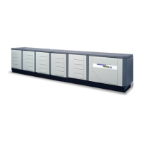
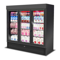
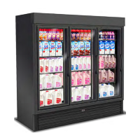
Merchandisers
Electrical requirements and power supply
Electrical connections tight and clean
Proper fan operation
Thermostat setting.
Walk-in coolers and freezers
Electrical requirements and power supply
Electrical connections tight and clean
Proper fan operation
Thermostat setting.
Condensers
Electrical requirements and power supply
Electrical connections tight and clean
Proper fan operation
Thermostat or pressure settings
Damper operation, if equipped.
Heat Reclaim and other systems
Electrical requirements and power supply
Electrical connections tight and clean
Component operation.
Note: Remember to reinstate control to
unit components jumpered to make tests.
Set all mechanical pressure controls.
Compressors should still be isolated from the
rest of the system. Set all electronic compres-
sor controls into switchback so the mechanical
controls are in command of all system func-
tions.
During the last evacuation look up and make a
list of the required control settings for the sys-
tem. A copy of the equipment legend will be
needed to determine the system's design oper-
ating points. High and low pressure, heat
reclaim lockout, winter control settings, and
other controls on the system should be noted.
Charging
Open
Compressors—Backseat Service Valves on
Suction and Discharge. Open oil supply line
immediately downstream of the Turba-shed.
Pressure Transducers—Open Angle Valves.
Leave Isolated
A u t o s u rge Pilot Valve—Leave Angle Va l v e s
closed on suction and discharge manifolds
until system stabilizes.
Connect
Defrost Time Clock—Connect power to the
clock and set to proper time.
Leave Open
Ball valves—to branches, condenser, heat
reclaim, receiver.
Main Liquid Line Solenoid Va l v e — N o w
under control of defrost clock.
Branch Liquid Line Solenoid Va l v e — B a c k
out manual open screws.
Suction Stop EPR or CDA Va l v e s — S u c t i o n
Stop EPR under control of defrost clock.
C D A Valves replace fuse in panel board to
place under control of defrost clock.
Split Condenser—Operating under pressure
controls.
Check
Oil levels for all compressors and Turba-shed.
HUSSMANN CORPORATION • BRIDGETON, MO 63044-2483 • Printed in USA
Revised August 1, 1996 P/N 340272A
9 - 3
Never trap liquid refrigerant
between closed valves.
Hydraulic explosion
may result.
Warning