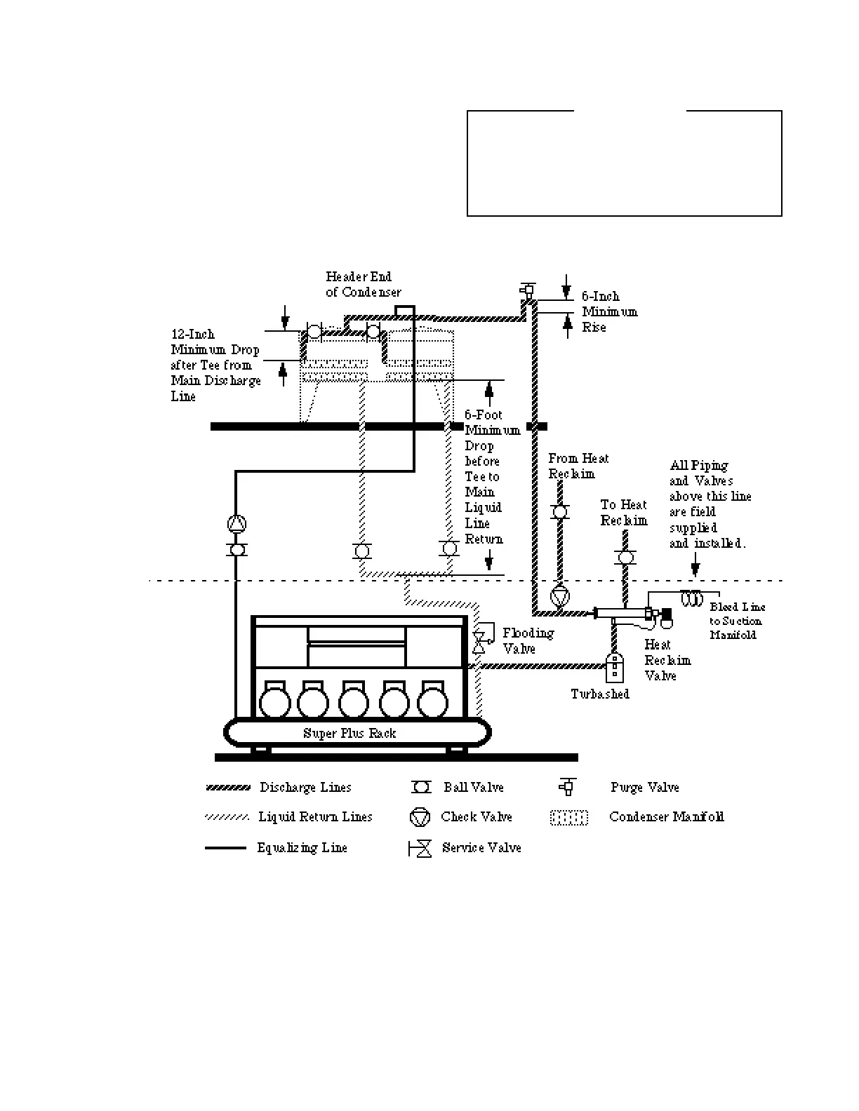
RACK TO CONDENSER PIPING
Connecting to One Manifold
• D i s c h a r ge Line will be routed directly to the con-
denser inlet stub with a purge valve at the highest
p o i n t .
•Liquid Return Line will be pitched downstream,
and provide trapless drainage to the Super Plus.
Equalizing Line (WHEN REQUIRED)
A
7
⁄8-inch equalizer line is piped between the
Receiver and the Condenser. A Check Va l v e
allowing flow only to the Condenser and a
shut off valve upstream of the Check Va l v e
will be field supplied and installed.
Purge Valve Location
The purge valve will be installed at the high-
est point of an inverted P-trap, with at least a
6-inch rise. Use with approved recovery
vessel.
HUSSMANN CORPORATION • BRIDGETON, MO 63044-2483 • Printed in USA
Revised April 15, 1997 P/N 340272A
3 - 3
Vent the Receiver
Safety Relief Valve
properly.
WARNING