OVERVIEW
This section is limited to the information
needed to set the Super Plus™ Compressor
Rack. Power Supply requirements are found
under “Electrical”; piping, under “Piping”;
and charging, under “Startup and Mainte-
nance”. Auxiliary units are found in the
sections devoted to them or in the manuals
accompanying them.
SUPER PLUS™ COMPONENTS
Each Super Plus contains the following:
1. Two to eight Copeland, or two to seven
Carlyle semi-hermetic compressors with
a. High and Low Pressure Controls
b. Oil Pressure Safety Control
c. Primary Overload Protection
d. Compressor Cooling Fans on low
temperature application, or
3
⁄4 to 3 HP
rating on Copeland air cooled
compressors
2. Factory piping with
a. Suction, Discharge and LiquidHeaders
b. Turba-shed Oil Separator and return
system
c. Dual Receiver Tanks
d. Suction Filters on each compressor
e. Liquid Filter Drier and Sight-glass
f. Liquid Level Indicator
3. Factory-wired control panel with
a. Pre-wired Distribution Power Block
b. Individual component Circuit Breakers
and Contactors
c. Compressor Time Delays
d. Color-coded wiring system
e. Customized wiring diagram
4. Items supplied separately for field
installation
a. Liquid Drier Core
b. Vibration Isolation Pads (8)
c. Loose shipped items for accessories.
Revised August 1, 1996 P/N 340272A
1 - 1
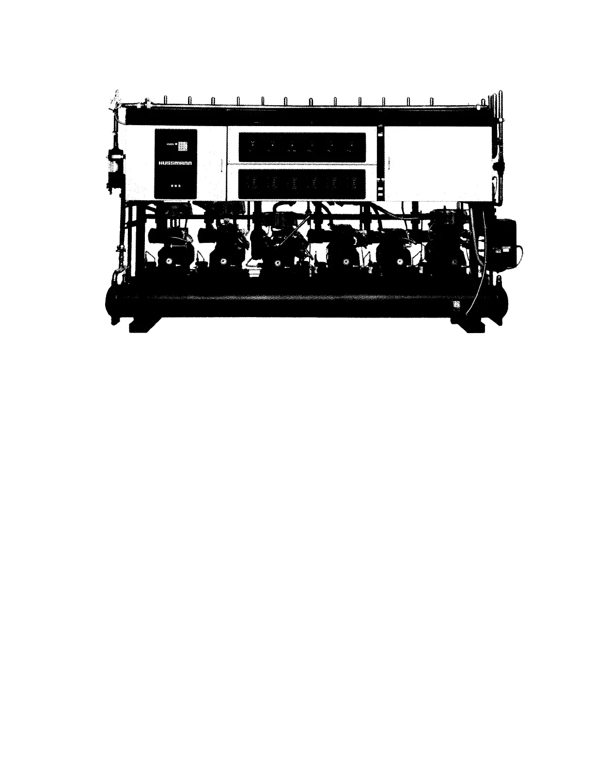
Figure 1-1 – Super Plus™ System
INSTALLATION INSTRUCTIONS
HUSSMANN CORPORATION • BRIDGETON, MO 63044-2483 • Printed in USA