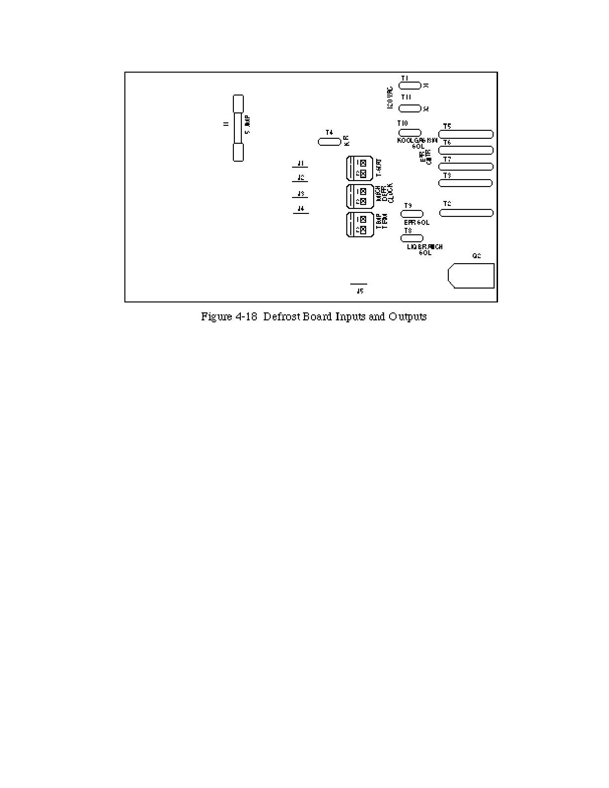
F U S E , 5A on circuit board can only be
replaced by removing board from panel.
Remove the screw on the front and on the top
of the faceplate.
J1 through J5 Jumpers should be clipped for
the following conditions:
J1 if thermostat controls EPR solenoid
J2 for Koolgas defrost
J3 and J1 for Off-time/Electric defrost (Do
not clip J1 if suction stop EPR is used.)
J4 if mechanical defrost time clock is used
J5 if Fibertronic Defrost Clock 1000 is used
T-STAT is input for temperature control ther-
mostat.
MECH DEFR CLOCK is input from the
normally open contacts on the mechanical
defrost clock, when contacts close branch
relay R1 will switch into defrost.
TEMP TERM is input from defrost termina-
tion thermostat – closes to end defrost.
X1 and X2 are 120VAC input to the board and
defrost branch. X1 is Line and X2 is Neutral
.
KR is output to Koolgas Relay
K G / 3 W S O L is output to the Koolgas or 3-
Way Valve Solenoid, depending on which is
applied.
EPR CNTR is input from case thermostat
when controlling the suction stop solenoid for
temperature. J1 must be cut.
EPR SOL is output to the suction stop sole-
noid valve.
LIQ BRANCH SOL is output to the liquid
branch solenoid valve.
Q 2 is fiber optic input from Fibertronic
Defrost Clock 1000.
HUSSMANN CORPORATION • BRIDGETON, MO 63044-2483 • Printed in USA
Revised August 1, 1996 P/N 340272A
4 - 23