MACHINE ROOM REQUIREMENTS
•The equipment room floor must solidly
support the compressor unit as a live load.
Ground level installation seldom presents
problems, but a mezzanine installation must
be carefully engineered.
• Ventilation should be 100 cfm per
compressor unit horsepower. The air inlet
should be sized for a maximum of 600 fpm
velocity. The ventilation fans should cycle by
thermostatic control.
•All machine room ventilation equipment
must be field supplied. Check local codes for
variances.
•Proper ventilation provides airflow across the
compressors. Duct work may be necessary.
•Provide a floor drain for disposal of
condensate that may form on the compressor
unit or header defrost assembly.
•Equipment must be located in the machine
room to provide enough working space for
service personnel, and to meet electrical codes.
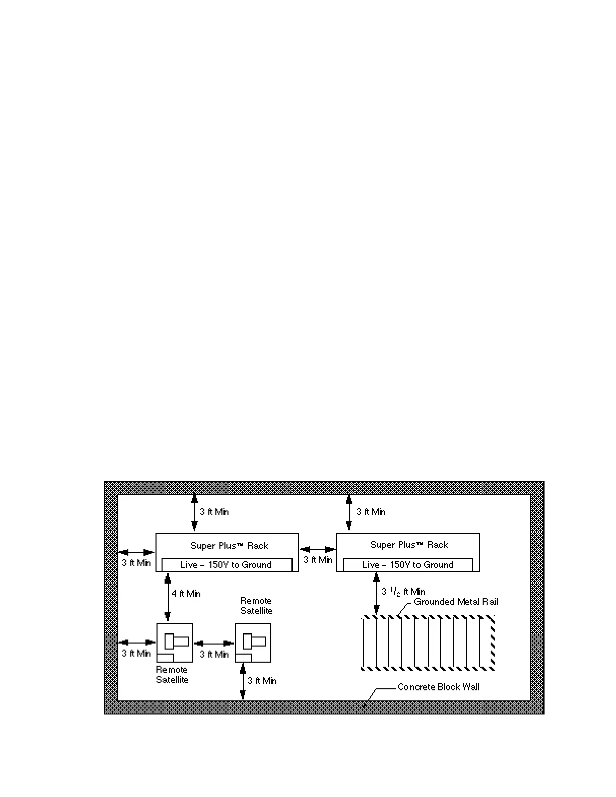
•Consult NEC National Fire Handbook
particularly “Installation of Switch Boards”
and “Working Space Requirements”. The
figure below demonstrates some suggested
distances. Refer to local codes for each
installation.
Super Plus Load Points (Center to Center)
Rack Assembly Load Point Dimensions
Nomenclature Length Width
(in.) (in.)
01VK, 02VK, 04VY 51 30
03VK, 04VK, 05VY 64.5 30
05VK, 06VK, 06VY 87 30
07VK, 08VK, 07VY 109.5 30
08VY 66 & 66 30
N o t e : The 08VY and other Extended Rack
have three cross feet and six load points, not the
usual two and four. For nonstandard racks such
as with mechanical subcooling consult
Hussmann Engineering, Bridgeton, Mo.
Revised August 1, 1996 P/N 340272A
1 - 3
HUSSMANN CORPORATION • BRIDGETON, MO 63044-2483 • Printed in USA