OTHER CONTROLS
Each control panel is wired with independent
compressor control circuits so any compressor
can be electrically isolated without causing the
other compressors to be shut down.
Time Delays
Automatic time delays on the Super Plus™
System help avoid electrical overload or com-
ponent damage. Awareness of time delays will
reduce confusion in starting and troubleshoot-
ing the system.
H u s s m a n n ’s EPC-2000 provides both anti-
short cycle and stagger-start delays. During
switchback operation when the EPC-2000 is
not controlling the system, sensible delays,
safeties and controls can maintain less
efficient operation. These backup systems are
tailored to individual customers. Check the
store legend for component listing
Alarm Delays
Alarm delays are used where trip points
are passed in normal operation, yet system
damage would result if cause continued
beyond the timed delay.
Compressor oil pressure failure
Copeland—120 seconds ±15 seconds
Carlyle—60 seconds ±15 seconds
Low liquid level—30 minutes
High suction level pressure—30 minutes
(for EPC-2000 not needed or recommended)
Faulty defrost timer motor—30 minutes
(not available with Paragon timer)
Copeland Solid-state Delay
Copeland compressors equipped with an inter-
nal solid-state protector cycle 120 seconds
after power break.
Thermostats
EVA P O R ATO R MO U N T E D LI Q U I D LI N E SO L E N O I D
Wire the thermostat in series with the liquid
line solenoid. Any 120V uninterrupted power
supply may be used.
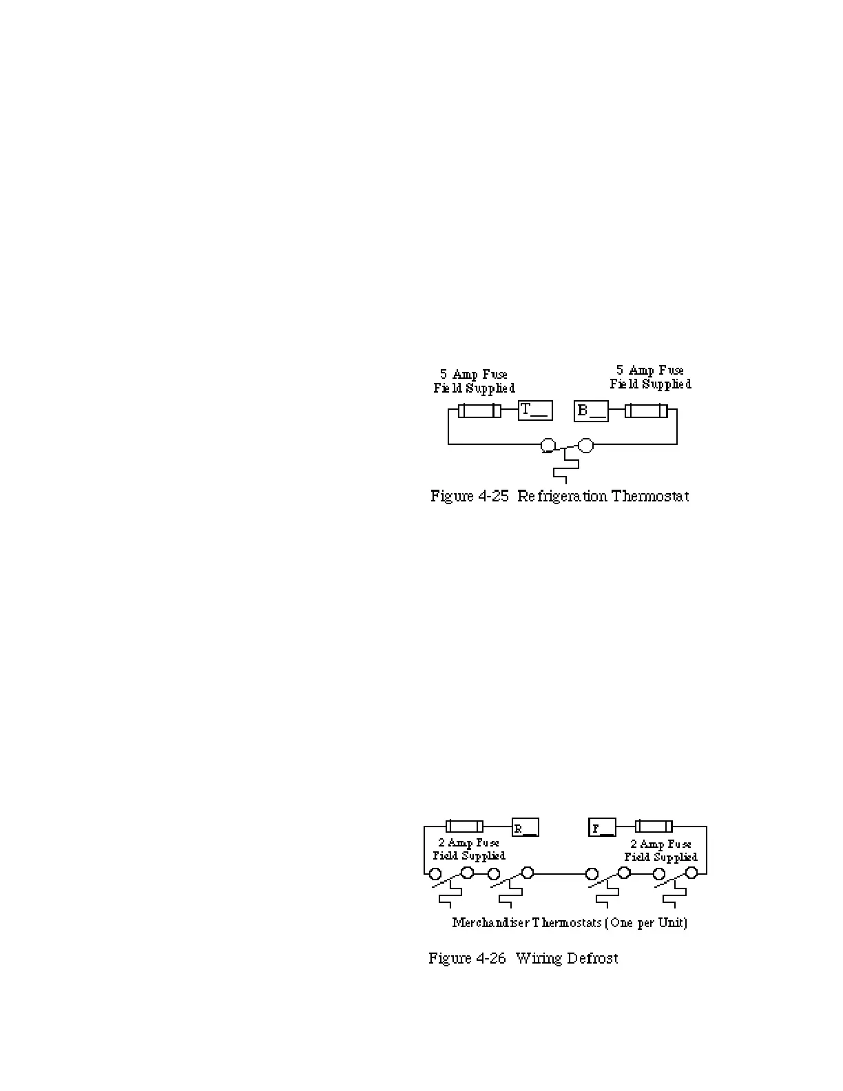
HEADER MOUNTED LIQUID LINE SOLENOID
Wire the thermostat in the following manner.
Determine the system number from the store
legend. In the control panel the system num-
ber matches the suffix of the appropriate “T”
and “B” terminals.
Remove the jumper between T_ and B_ terminals.
Connect one thermostat wire to the T_ terminal.
Connect the other wire to the B_ terminal.
Defrost Termination Thermostats
For each system using defrost termination
thermostats, run one 2-wire control circuit
placing all termination thermostats in series
and connected between the R_ and F_ termi-
nals in the control panel with the suffix
corresponding to the system number. Check
the store legend for system number.
HUSSMANN CORPORATION • BRIDGETON, MO 63044-2483 • Printed in USA
ELECTRICAL Revised August 1, 1996
4 - 32