WIRING GUIDELINES BASED ON
VARIOUS COMPONENTS
Check the store legend for components requir-
ing electrical circuits to either the compressor
unit or the defrost control panel. These include:
– Defrost termination thermostat
– Thermostat controlling a header mounted
liquid line solenoid
– C D A temperature control
– ETR temperature control
– Satellite control
All thermostat and temperature sensor wires
should be sized for pilot duty at 120VA
1 2 0 VAC. Run a 2-wire circuit for each system
using any of the five controls listed above.
Unit Cooler Fan Wi r i n g
Provide a 120/1/60 fused power supply for
each cooler. (Check the store legend to see if
208-230/1/60 is required at this location.)
E v a p o r a t o r Mounted Liquid Line Solenoid
Power for a liquid line solenoid in the case can
be picked up from the fan circuit. (Check fan
motor and solenoid voltages first.)
Select Wire Size
Based on the serial plate ampacity of the sys-
tem, select the largest connectable wire size
from Table 1.
Cooler Door Switch Wiring
Check the store legend for door switch kits
(M115 or M116). The switch must be mount-
ed to the cooler door frame, and must be
wired to control the field installed liquid line
solenoid and the fan circuit. For Koolgas
applications, kit M116 includes a check valve
to bypass the liquid line solenoid valve.
Sizing Wire and Overcurrent Protectors
Check the serial plate for Minimum Circuit
Ampacity (MCA) and Maximum Overcurrent
Protective Devices (MOPD). Follow NEC
guidelines.
Defrost Controls
These circuits may be repeated and/or inter-
mixed in one store.
Other Controls
When other controls are used, refer to the
manual included with that control.
HUSSMANN CORPORATION • BRIDGETON, MO 63044-2483 • Printed in USA
ELECTRICAL Revised August 1, 1996
4 - 2
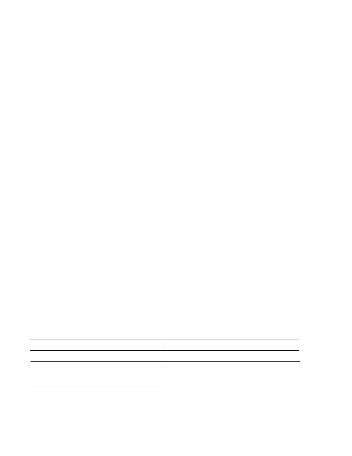
Table 1. Required Field Wire Size
*Include control circuit amps if single point connection transformer option is used
12A for 208V systems
6A for 460V systems
(Refer to NEC for temperature derating factors.)
TOTAL CONNECTED MCA* LARGEST CONNECTABLE WIRE
(Based on no more than 3 wires in the 75
O
C Wire Rating 50
O
C
raceway and 3 0
O
C environment per NEC.)
140A (max) 00 per Phase
248A (max) 350 mcm per Phase
408A (max) 2 x (250 mcm) per Phase
608A (max) 2 x (500 mcm) per Phase