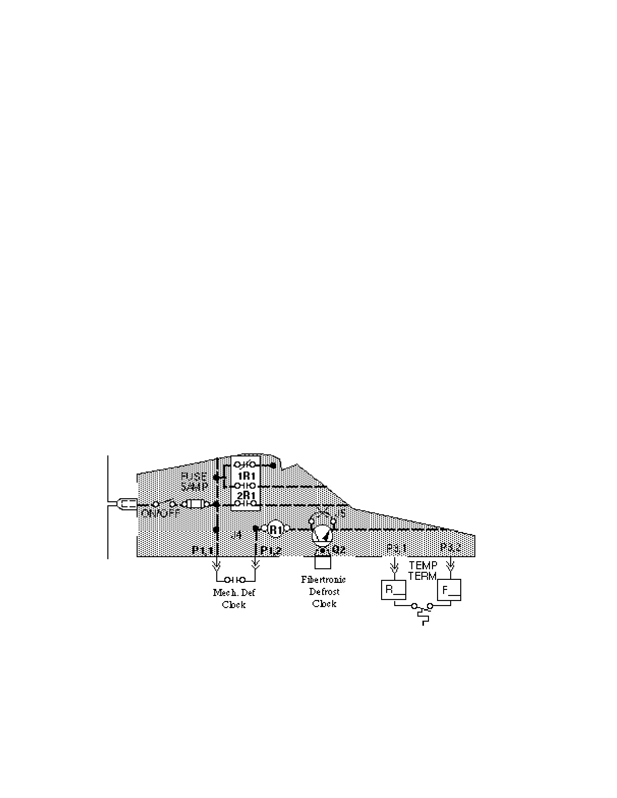
DEFROST TIMER MOTOR
Timer motors are wired directly between “X1B”
and neutral “X2F”, so they are energized unless:
-Power fails
-Control Panel Circuit Breaker is open
-Single Phasing Protector opens.
DEFROST CONTROL CIRCUITS
The different defrost systems shown on the
wiring diagrams all work from the same basic
circuit. The variations come from tailoring the
systems to the customers’ needs by selection of
components used to accomplish defrost.
The basic circuit is controlled by a defrost
clock which closes the circuit, energ i z i n g
relay coil R1. R1 controls one contact 1R1
(normally closed) and two contacts 2R1 (nor-
mally open). NC 1R1 controls refrigeration
components. NO 2R1’s control defrost com-
ponents. As the system requirements vary so
will the components controlled by the con-
tacts.
Once begun, defrost continues until the
defrost termination thermostat or defrost clock
opens the defrost circuit de-energizing relay
coil R1.
HUSSMANN CORPORATION • BRIDGETON, MO 63044-2483 • Printed in USA
ELECTRICAL Revised August 1, 1996
4 - 28