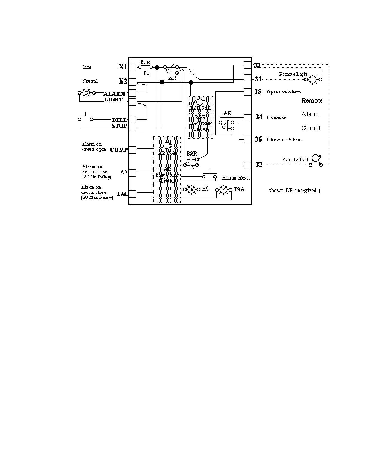
Schematics show Sequence of Operation.
Electronic circuit logic is omitted, since print-
ed circuits are not field repairable.
Sequence of Operation
Control Panel 120V circuit closes
Power to X1 energizes Alarm Relay (AR)
AR Electronic Circuit energizes
AR Coil
AR Contacts open
between Terminals 34 and 36
after Fuse F1
AR Contacts close
between Terminals 34 and 3 5 .
The closed Compressor Alarm Circuit inputs
1 2 0 V at Terminal C O M P. If the circuit opens
AR Coil DE-energizes
AR Contacts open
between Terminals 34 and 3 5 .
AR Contacts close
between Terminals 34 and 36
after Fuse F1
Energizing
Alarm Light, Bell Stop Switch,
Terminals 31 and 3 2 .
The A9 and T 9 A circuits remain open during
normal operation. If either circuit closes a 120V
input to the Alarm Board activates A9 or T 9 A
LED and Alarm Condition.
AR Coil DE-energizes
AR Contacts open
between Terminals 34 and 3 5 .
AR Contacts close
between Terminals 34 and 36
after Fuse F1
Energizing
Alarm Light, Bell Stop Switch,
Terminals 31 and 3 2 .
With A9 or T 9 A the Board will remain in A l a r m
until the Reset is pressed or power turn o ff / t u r n
on is used.
The Bell Stop Relay (BSR) circuit may operate
only during Alarm Conditions. When the Bell
S t o p Switch is closed
B S R Electronic Circuit energizes
BSR Coil
BSR Contacts open
the circuit to Terminal 3 2
BSR Contacts close
the circuit for its own power supply.
HUSSMANN CORPORATION • BRIDGETON, MO 63044-2483 • Printed in USA
Revised August 1, 1996 P/N 340272A
4 - 3
USING SCHEMATICS
Figure 4-1 Alarm Board Circuits