Figure 7-20. Dierential Valve Assembly .................................................................. 7-32
Figure 7-21. Recovery Tank Cover Assembly .......................................................... 7-33
Figure 7-22. Vacuum Relief Valve Assembly ............................................................ 7-34
Figure 7-23. Water Box Assembly - View 1 of 2 ...................................................... 7-35
Figure 7-24. Water Box Assembly - View 2 of 2 ...................................................... 7-36
Figure 7-25. Diuser Filter Assembly ....................................................................... 7-38
Figure 7-26. Float Valve Assembly ........................................................................... 7-39
Figure 7-27. Dura-Flow Automatic Pump Out (APO) - Production Assembly ........... 7-40
Figure 7-28. Salsa Heat Exchanger Assembly (Chevy) ........................................... 7-42
Figure 7-29. Non Salsa Heat Exchanger Assembly ................................................. 7-44
Figure 7-30. Yaw Sensor Cooling Kit Assembly (Chevy) .......................................... 7-45
Figure 7-31. Horizontal Pump In Tank Assembly - View 1 of 2 ................................. 7-46
Figure 7-32. Horizontal Pump In Tank Assembly - View 2 of 2 ................................ 7-47
Figure 7-33. 120 Gallon Pump-In Tank Fitting Assembly ........................................ 7-49
Figure 7-34. 85 Gallon Rotomold Fresh Water Tank Assembly - View 1 of 2 ........... 7-50
Figure 7-35. 85 Gallon Rotomold Fresh Water Tank Assembly - View 2 of 2 ........... 7-51
Figure 7-36. Pass Though Assembly ........................................................................ 7-53
Figure 7-37. Chevy Cowling Assembly ..................................................................... 7-54
Figure 7-38. Ford Cowling Assembly........................................................................ 7-55
Figure 9-1. Electrical Schematic ................................................................................. 9-3
Figure 9-2. Wiring Diagram - View 1 of 2 .................................................................. 9-4
Figure 9-3. Wiring Diagram - View 2 of 2 ................................................................... 9-5
Figure 10-1. Zerk Fittings on Drive Shaft (Chevy and Ford)..................................... 10-6
List of Figures
Table 3-1. GM Throttle Controller LED Functions ....................................................... 3-6
Table 3-2. Ford Throttle Controller Light Functions .................................................... 3-8
Table 7-3. Hose Routings ......................................................................................... 7-56
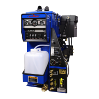
v - CDS 4.8 Owner’s Manual