TROUBLESHOOTING AND SYSTEM TESTS
powermax
65/85
Service Manual 5-13
IGBT test preparation
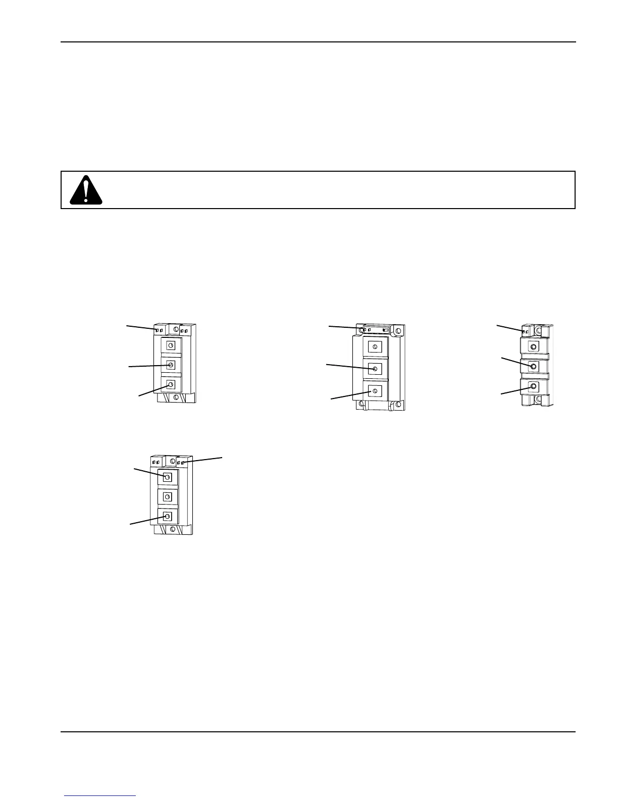
Before testing with the Hypertherm IGBT tester, connect the colored leads to the IGBT as shown on the next page.
Note: Before an IGBT can be tested, it must be electrically isolated from all circuits. If the IGBT is installed in a
power supply, remove the power board and any lead connections before testing.
The illustrations below depict three common configurations of an IGBT. Each connection on the IGBT will be labeled
with an abbreviation. They may be labeled as C, E, G or 1, 2, 3 with a schematic that shows numbers and pin functions.
Yellow lead
Gate 2 (G2)
Black lead
Emitter 2 (E2)
Red lead
Collector 2, (C2)
IGBT, Inverter
Test 1
Yellow lead
Gate (G)
Black lead
Emitter (E)
Red lead
Collector (C)
IGBT, PFC
Yellow lead
Gate (G)
Red lead
Collector (C)
Black lead
Emitter (E)
IGBT, Pilot arc
IGBT, Inverter
Test 2
Yellow lead
Gate 1 (G1)
Red lead
Collector 1, (C1)
Black lead
Emitter 1 (E1)
Caution: Failure to isolate the IGBT may result in false readings and/or damage to the
IGBT tester.