TROUBLESHOOTING AND SYSTEM TESTS
powermax
65/85
Service Manual 5-39
BLK
BLK
J13
Test 1 – Voltage input
Symptom: Voltage fault (0-60-0, -1 or -2)
• Check the line voltage at the power switch (S1).
• Check the input voltage to the input diode bridge.
- The AC voltage between any 2 input wires should equal the line voltage.
• If there is proper voltage to the power switch, and low voltage to the input diode, replace the power switch.
• Check the output voltage of the input diode bridge.
- Output VDC = Line Voltage x 1.414 VDC.
Note: All values are ±15%.
Three phase
L1 Black (CSA)
Brown (CE)
L2 White (CSA)
Black (CE)
L3 Red (CSA)
Gray (CE)
PE Green (CSA)
Green/Yellow (CE)
LV
LV/1.732
LV
LV
LV X 1.414
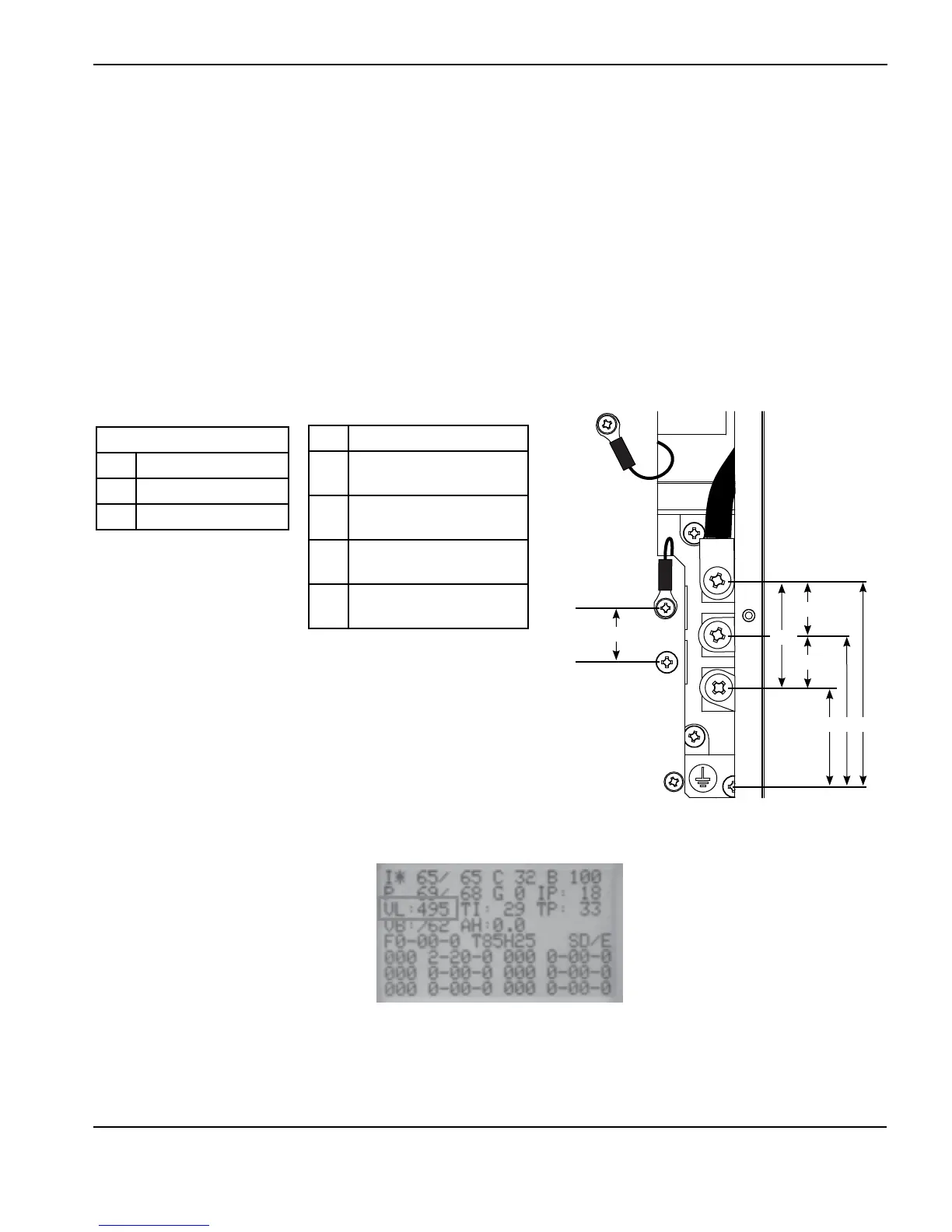
• If there is a fault and the diode bridge output value is correct:
- Display the service screen and confirm that the value “VL” is ±15% of AC line voltage.
LV = incoming line voltage
• If there is a fault and the “VL” value is correct:
- Verify the DSP board by replacing it with a known good board.
- If DSP board is not the problem, replace the power board and the PFC IGBT (CSA units only).
Single phase
L Black (CSA)
N White (CSA)
PE Green (CSA)