COMPONENT REPLACEMENT
powermax
65/85
Service Manual 6-11
Replace the work lead
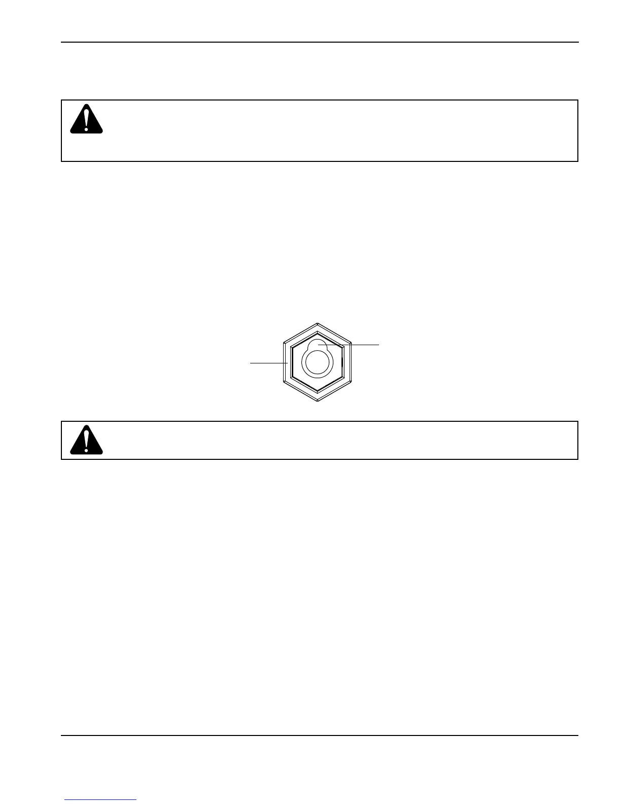
Work lead receptacle
on power supply
Keyed opening at
top of receptacle
1. Turn OFF the power.
2. Remove the old work lead from the front of the power supply. Turn the work lead connector counterclockwise
approximately 1/4 turn.
3. Pull the work lead connector out of the receptacle.
4. Insert the new work lead connector into the receptacle.
Note: The receptacle is keyed. Align the key on the work lead connector with the opening at the top of the
receptacle on the power supply.
Caution: Make sure you use a work lead that is appropriate for your power supply.
Use a 65A work lead with the Powermax65. Use an 85A work lead with the
Powermax85. The amperage is marked near the rubber boot of the work lead
connector.
Caution: Ensure the work lead is fully seated in the receptacle to prevent overheating.
5. Push the work lead connector all the way into the receptacle on the power supply and turn clockwise, approximately
1/4 turn, until the connector is fully seated against the stop in order to achieve an optimal electrical connection.