TROUBLESHOOTING AND SYSTEM TESTS
5-48 powermax
65/85
Service Manual
Test 6 – Torch stuck open (TSO)
Symptom: No fault occurs at power-up but an 0-30 fault displays on the operator screen when attempting to fire the
torch.
Confirm that all of the proper consumables are installed in the torch.
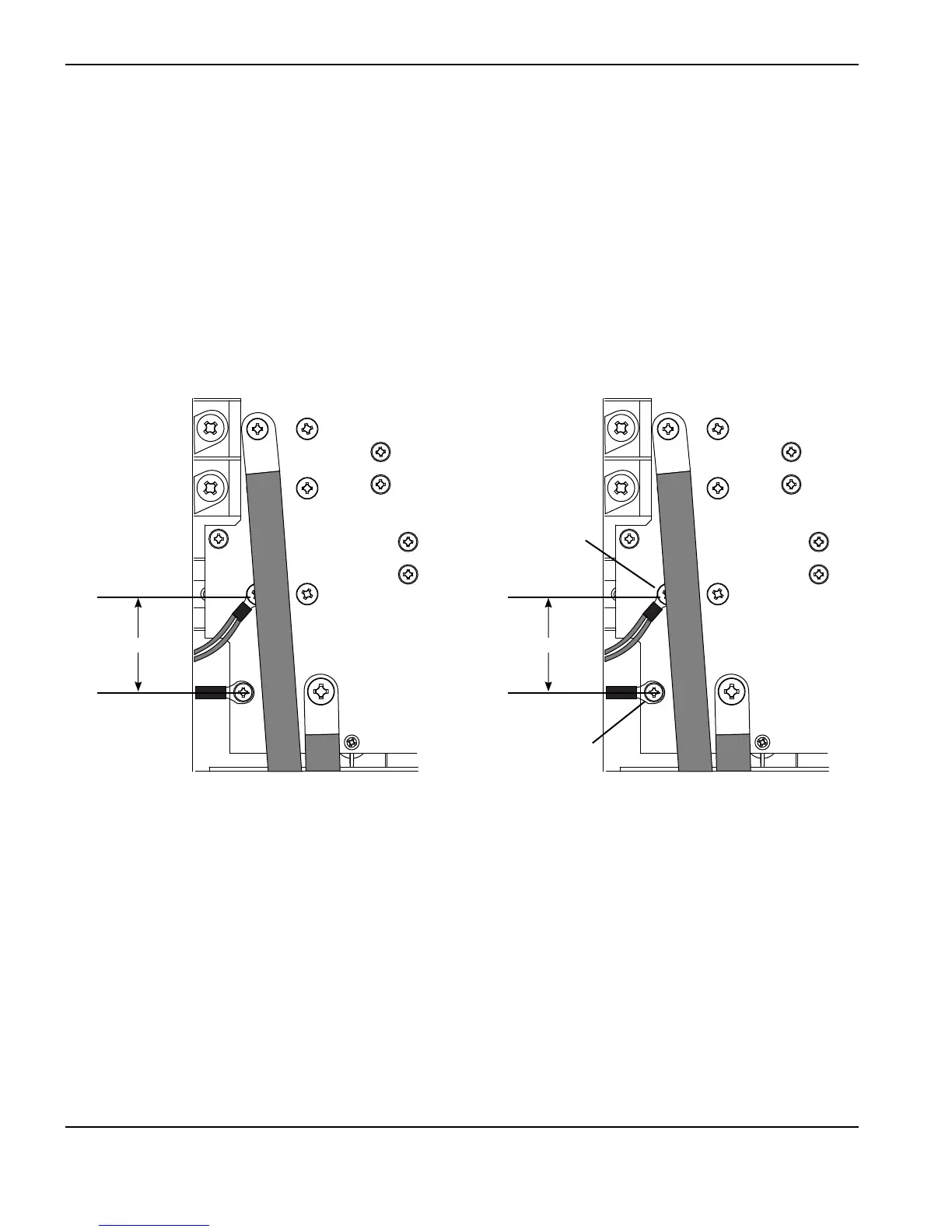
In an idle (no start signal) working system with the torch and consumables installed, there should be continuity between
the dual black wires connected to the center post of the pilot arc IGBT and the red wire connecting to J28. With gas
flowing through the torch (gas test mode 1) there should be very high resistance between those two points.
Note: To set the system to gas test mode, display the service screen (refer to page 5-21 Displaying the service screen),
move the cursor to “G” (gas), and use the adjustment knob to toggle to “1” (gas test mode).
WORK
LEAD
J26
J28
WORK
LEAD
J26
J28
Gas test mode 0 Gas test mode 1
<5 Ω >10 kΩ
Continuous with
the nozzle or torch
outer body
Continuous with
system negative