COMPONENT REPLACEMENT
6-4 powermax
65/85
Service Manual
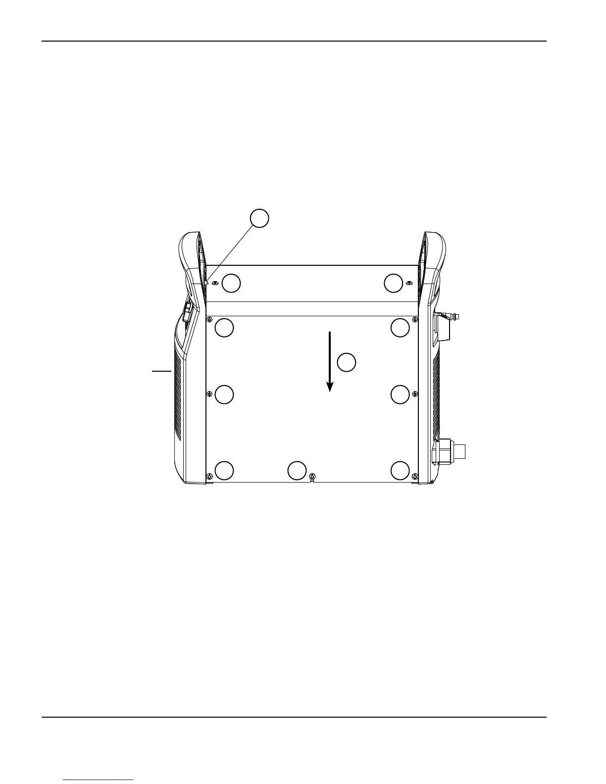
Replace the power supply cover
1. Place the cover (3) over the power supply with the slot in the cover (4) over the plastic tab in the front panel. The
slot and tab ensure that the vent in the side of the cover is over the fan. Be careful not to pinch any wires.
2. Using a T15 TORX or blade screwdriver, install the 8 small screws (2) into the power supply cover. Tighten the
screws to 15 in-lbs (17.3 kg cm).
3. Using a T20 TORX or blade screwdriver, install the 8 large screws (1) into the power supply cover. Tighten the
screws to 15 in-lbs (17.3 kg cm).
Front of
power supply
1
1 1
2
2
1
2
2
1
3
4