TROUBLESHOOTING AND SYSTEM TESTS
5-14 powermax
65/85
Service Manual
IGBT device test using the Hypertherm tester
Using the Hypertherm IGBT tester, press and hold the switch in the desired position to perform each test described in
the following table.
Switch LED
Position Fail Pass Battery This may mean Corrective action
Left X - - IGBT is short-circuited Replace IGBT
Left - X - IGBT passed the short-circuit test None
Left - - X Battery below 8V Replace battery
Left - - - Dead battery Replace battery
Right X - - IGBT is open Replace IGBT
Right - X - IGBT passed the open test None
Right - - X Battery below 8V Replace battery
Right - - - Dead battery Replace battery
Troubleshoot the Hypertherm IGBT tester
1. Inspect the leads and the IGBT tester for damage.
2. Verify that the battery voltage is greater than 8V.
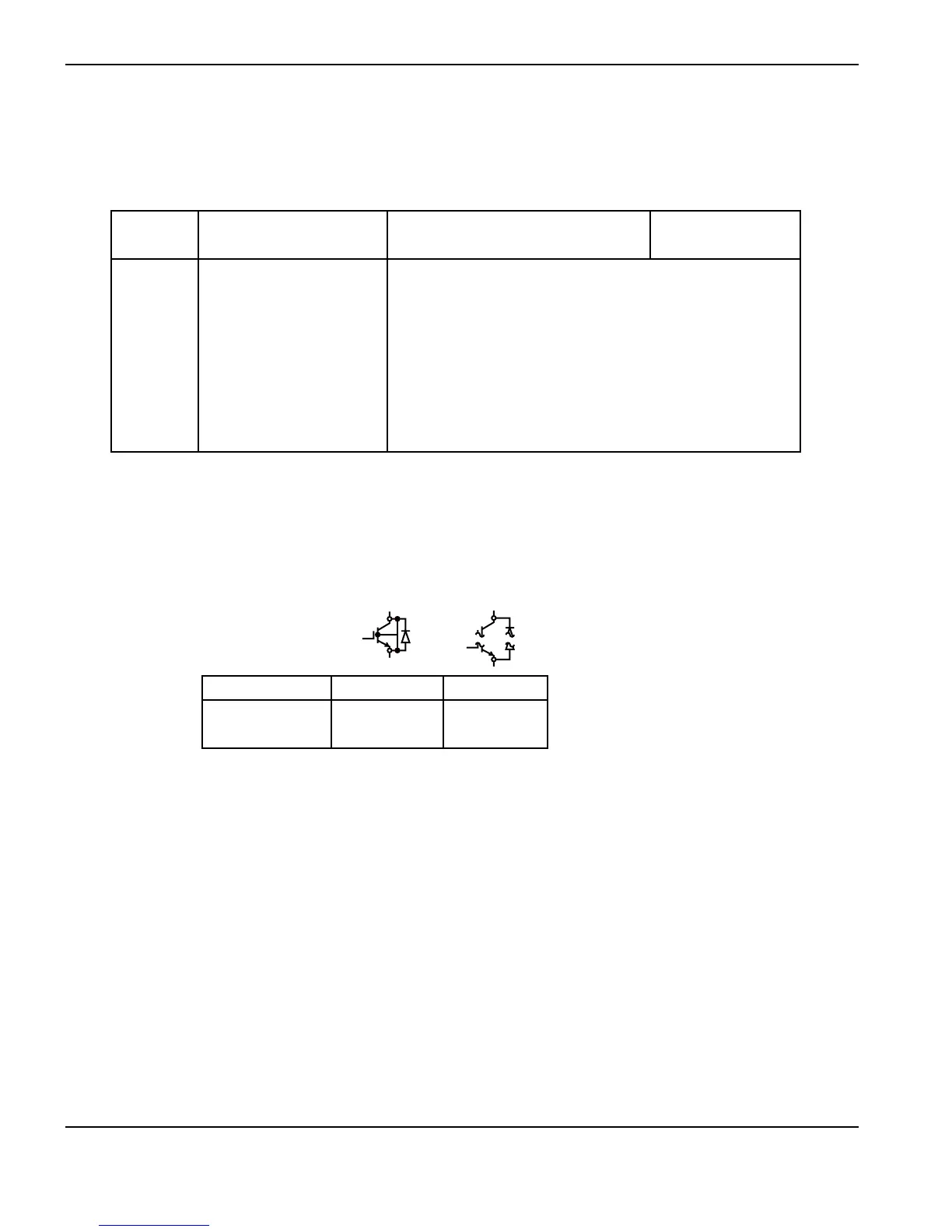
3. Test the IGBT Tester, itself, as shown below. If the results do not match the table, replace the lead connections.
Connect leads Short test Open test
None Pass Fail
Red to Black Fail Pass