TROUBLESHOOTING AND SYSTEM TESTS
powermax
65/85
Service Manual 5-41
WORK
LEAD
J13
J2 J1
J18J19
J27
J30
J23
J24
TP13
J29
TP11
TP12
WORK
LEAD
BLK
BLK
J13
J16J17J18J19
J26
TP12
J28
TP10
TP11
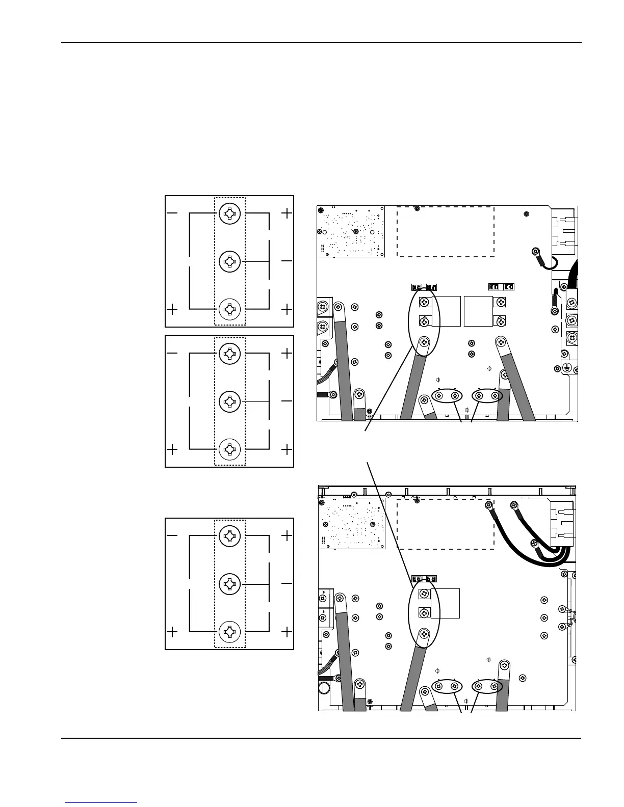
Voltage check
All voltages must be measured with the input power connected and the machine on.
Note: Wear proper personal protective equipment (PPE) before testing powered equipment. All values are ±15%.
• Check the inverter IGBT voltages as described below.
• The voltage measured across the bulk capacitors (half the buss voltage or the smaller values above) should be
the same before and during torch operation.
375 VDC
Bulk capacitors
Bulk capacitors
Inverter IGBT
module
425 VDC
280 VDC
750 VDC
850 VDC
560 VDC
375 VDC
425 VDC
280 VDC
CSA 200-480 VAC
input
CSA 600 VAC
input
CE 400 VAC
input
CSA
CE