TROUBLESHOOTING AND SYSTEM TESTS
powermax
65/85
Service Manual 5-45
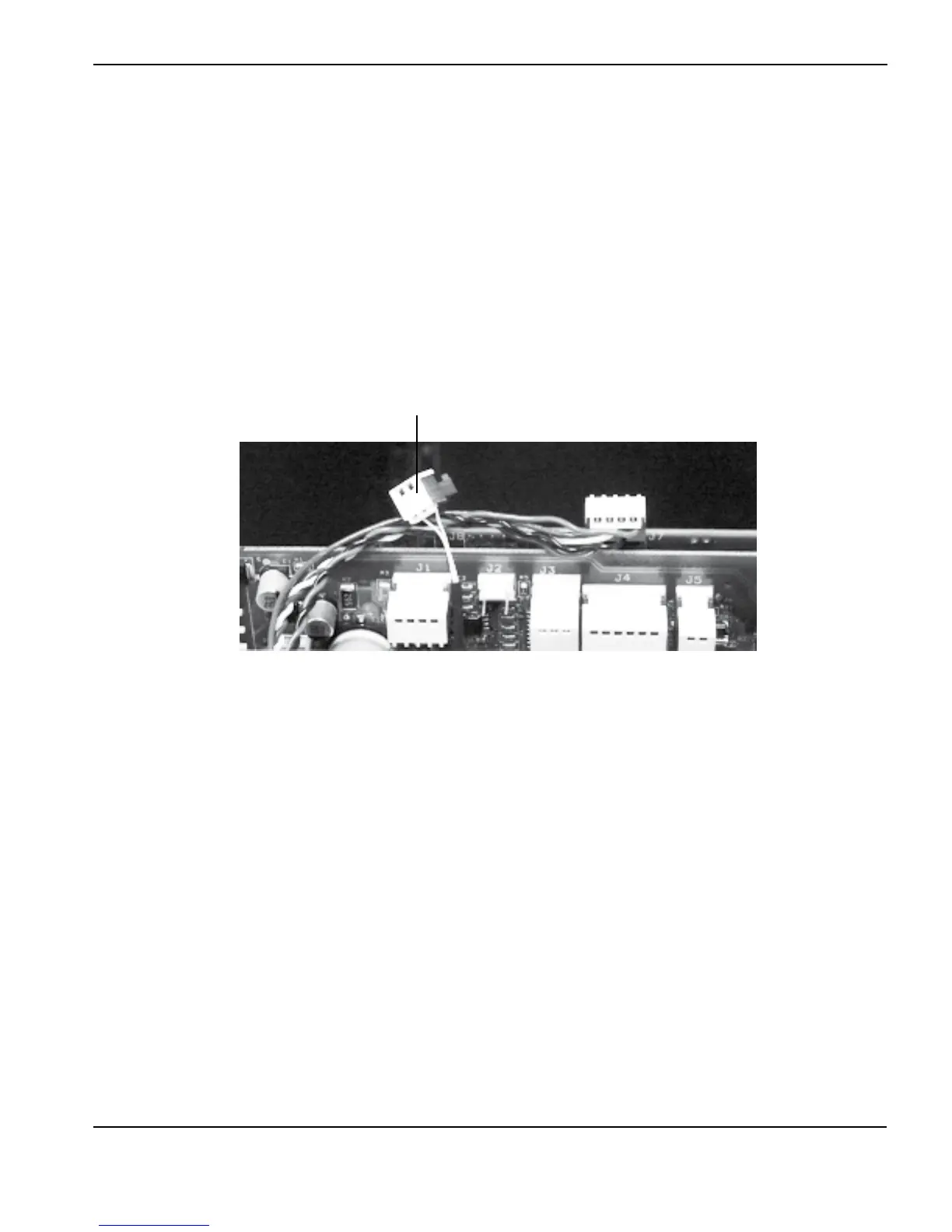
For operational fault codes 0-40-2 and 0-40-3 or power board faults 2-10-0 and 2-10-1
1. Remove the inverter temperature sensor connector from the top-rear of the power board (J2 on CSA units or J4 on
CE units).
2. Measure the resistance between pins 1 and 3 on the plug.
3. If the resistance is not within ±15% of 10 kΩ replace the temperature sensor.
4. If the value is correct, remove the DSP board and measure the resistance between pins 1 and 3 on the power board
with the temperature sensor disconnected. The resistance should be approximately 57.6 kΩ.
5. If the value is correct, replace the DSP board.
6. If the value is incorrect, replace the power board.
Inverter temperature
sensor connector