A
.
INSTALLATION MANUAL
FOR ELECTRICAL PARTS
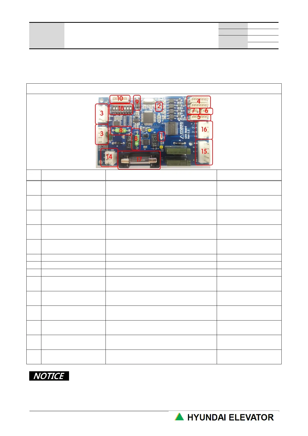
3.2 GH5 PC Board
Board for hall lantern and chime during the destination floor operation without a separate floor display
and group operation
When 24VDC is applied to the board power
side, it is turned ON.
It is OFF
when there is a problem.
It blinks when there is no problem with CAN
COMM.
It does not blink
when there is a problem.
Power / communication
connecting part
Connect for 24VDC and CAN
communication.
Connect the button to call the Car
at the corresponding floor.
Hall chime / hall lantern
Connect when hall chime / hall lantern is
used.
Connect and apply for program UPDATE.
Connect the cable at parking floor.
Connect to firefighter call (=FMR) switch.
When JUMP is released, it works as REAR
(=handicap) HIP.
In normal time,
JUMP is connected.
110VAC power for external lantern and
chime
Separate 110VAC
lantern connecting part
External lantern should use 110VAC.
Separate 110VAC
chime connecting part
External chime should use 110VAC.
It is destroyed when over-current is
supplied.
Check
when lantern is defective.
Input floor according to HEXA 8421 method.
Floor setting has the corresponding floor input at ship-out before delivering to the
site.
 Loading...