381
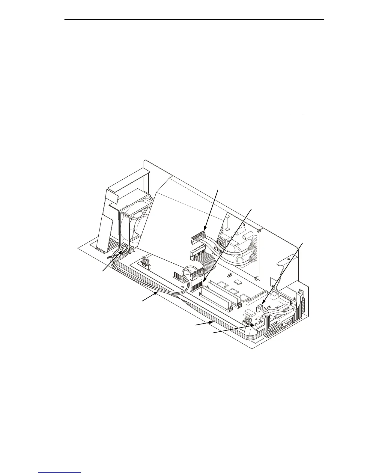
5. Connect the power stacker logic cable P103 to connector J17 on the CMX
controller board. (See Figure 73.)
6. Disconnect the power supply cable from connector J101 on the CMX
controller board. (See Figure 73.)
7. Connect power supply cable connector P101 to the stacker power cable,
then connect the stacker power cable to connector J101 on the CMX
controller board. (See Figure 73.)
8. Route the stacker power cable and the stacker logic cable in front
of the
CMX board and through the cutout beneath the card cage fan, as shown
in Figure 73.
Legend:
1. Power Supply Connector P101
2. CMX Board Connector J101
3. Connector P103
4. CMX Board Connector J17
5. Stacker Logic Cable
6. Stacker Power Cable
7. Cutout Beneath Card Cage Fan
Figure 73. Stacker Power and Logic Connections on the CMX Controller Board
1
2
3
4
5
6
7

 Loading...


