232 IBM eX5 Implementation Guide
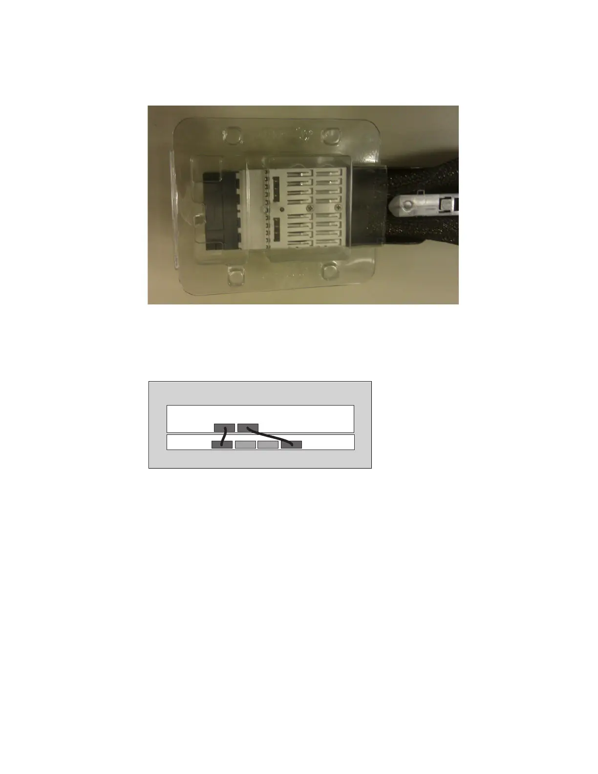
keep a set of these plastic boots for times when you want to remove the QPI cables for the
movement of equipment from rack to rack or for servicing the unit.
Figure 6-7 Reusable QPI cable connector protective boot
There are four QPI cables connecting all of the QPI ports of the x3850 X5 to all of the QPI
ports on the MAX5. Figure 6-8 shows how to connect the cables between the QPI ports of
the two units.
Figure 6-8 QPI cable installation
The QPI cables are keyed to only be inserted one way. A quick visual check for cable
orientation is to look for the 4U QPI or 1U QPI labels on the cable. The labels, along with
the blue retainer release tab, are placed on what becomes the visible top of the cable
when the cables are installed correctly.
The ends of the cables are labeled to indicate which end to insert into the correct
equipment. The 4U QPI end of the cables plugs into the x3850 X5. The 1U QPI end of the
cables plugs into the MAX5.
The cable end slides into the port until it clicks into place. You can disengage the retainer
that holds the cable in place by pressing on the blue tab on the top of the QPI cable
connection.
QPI cables for connecting QPI ports 1 to 1 and 4 to 4 must be installed, even when only
one processor is installed, to allow the MAX5 to be controlled by the server. If one of the
cables is detached, the server does not power on or complete POST.
You must install QPI cables for each of the processors installed to ensure full memory
access to the MAX5. Table 6-3 on page 233 describes the QPI port on the back of the
server with the corresponding processor socket in the server.

 Loading...


