Chapter 8. IBM BladeCenter HX5 375
8.1.2 Clearing CMOS memory
When a server is shipped from one location to another location, you have no idea what the
server was exposed to. For all you know, it might have been parked next to a large magnet or
electric motor and everything in the server that stores information magnetically has been
altered, including the CMOS memory. IBM does not indicate on the shipping carton that
magnetic material is enclosed, because the information is readily recoverable.
Booting the server to the F1 system configuration panel and selecting Load Default Settings
restores the default values for the items that you can change in the configuration. This option
does not change the settings of registers that are used by the Integrated Management
Module (IMM) and the UEFI. These registers define the system state of the server. When they
become corrupt, the server can display the following symptoms:
Fail to power on.
Fail to complete POST.
Turn on amber light path diagnostic lights that describe conditions that do not really exist.
Reboot unexpectedly.
Fail to detect all of the installed CPU, memory, PCIe adapters, or physical disks.
You cannot restore or modify these internal registers to their defaults by using the F1 system
configuration panel; however, you can restore these internal registers to their defaults by
clearing the CMOS memory.
There are two key ways to clear the CMOS. One method is by jumper and the second method
is by removing the CMOS battery. We describe each method in the following sections.
Jumper method
Use the following procedure to clear the CMOS using the jumper method:
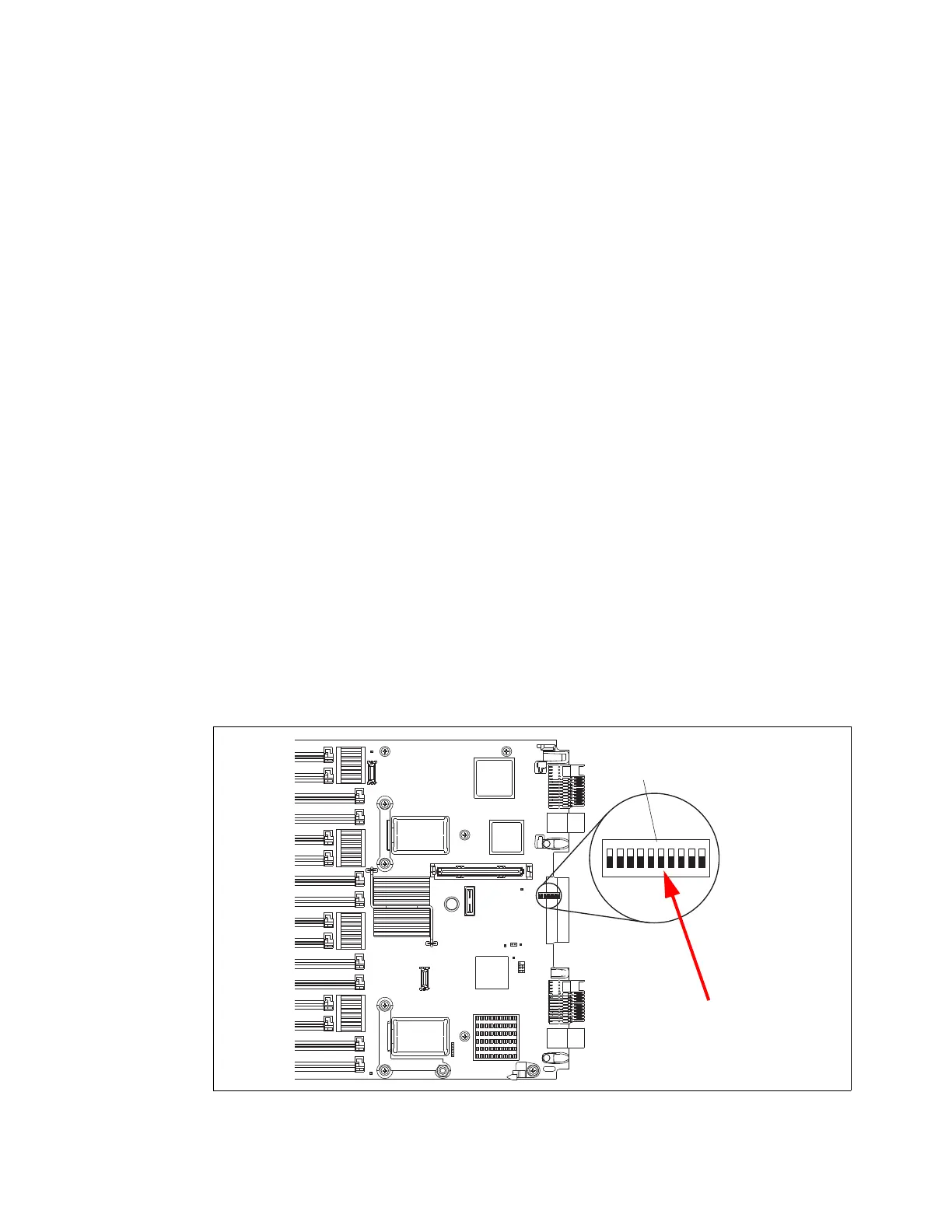
1. Power-cycle the real-time clock (RTC). Locate the switch block SW2 in the middle of the
system board at the extreme rear of the server, as shown in Figure 8-3. You must remove
all of the expansion cards to reach the jumper block.
Figure 8-3 Switch block SW2 location

 Loading...


