Chapter 3. IBM System x3850 X5 and x3950 X5 61
Figure 3-5 MAX5 connectors and LEDs
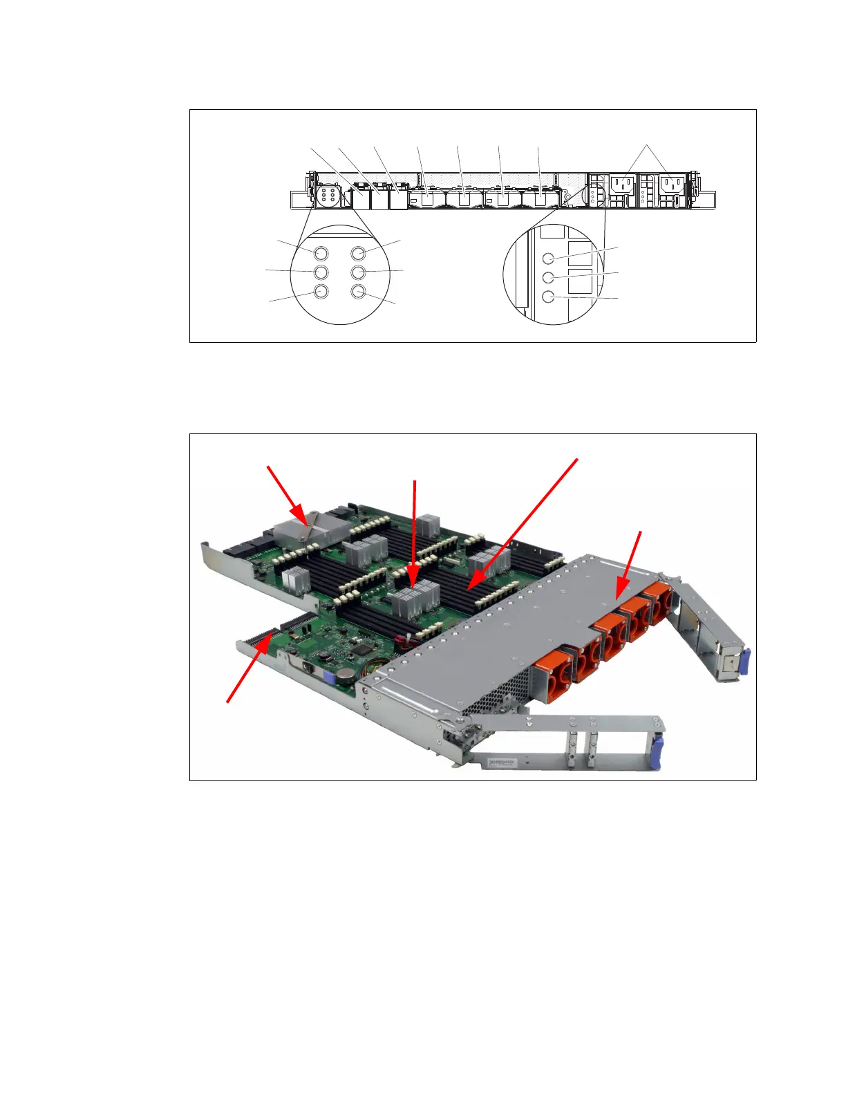
Figure 3-6 shows the internals of the MAX5 including the IBM EXA chip, which acts as the
interface to the QPI links from the x3850 X5.
Figure 3-6 MAX5 memory expansion unit internals
For an in-depth look at the MAX5 offering, see 3.5, “MAX5” on page 68.
3.1.4 Comparing the x3850 X5 to the x3850 M2
Table 3-1 on page 62 shows a high-level comparison between the eX4-based x3850 M2 and
the eX5-based x3850 X5.
Power-on
LED
Locate
LED
System
error
LED
AC LED (green)
DC LED (green)
Power supply
fault (error) LED
QPI
port 1
Power
connectors
EXA port 1
LEDlink
EXA port 2
LEDlink
EXA port 3
LEDlink
EXA
port 1
EXA
port 2
EXA
port 3
QPI
port 2
QPI
port 3
QPI
port 4
32 DIMM socketsIntel Scalable
Memory buffers
Five hot-swap
fans
MAX5 slides
out from the
front
IBM EXA chip
Power supply
connectors

 Loading...


