2-5
BASIC MANUAL
2
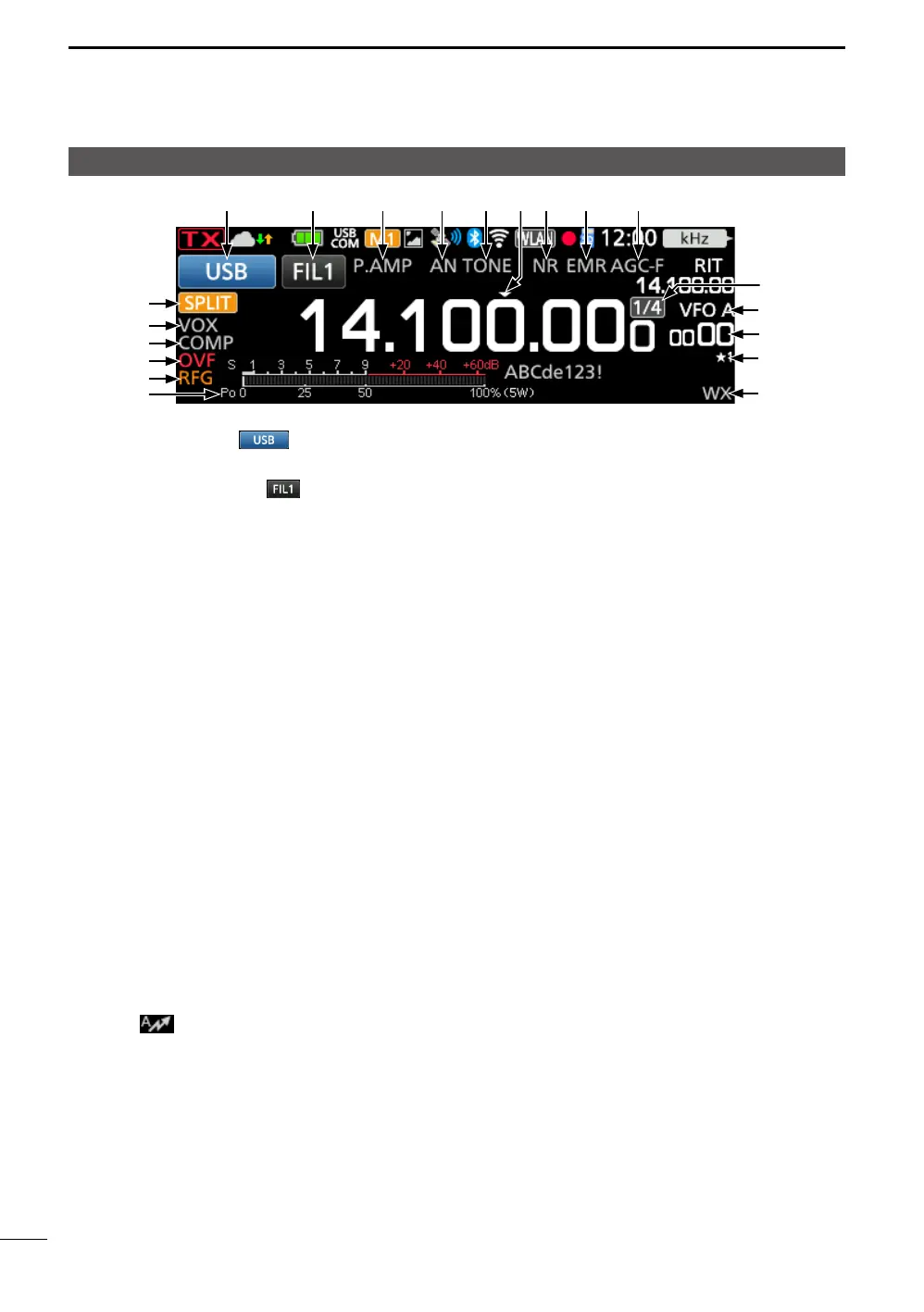
PANEL DESCRIPTION
MODE INDICATOR
(p. 3-2)
Displays the selected operating mode.
IF FILTER INDICATOR
(p. 4-5)
Displays the selected IF filter number.
LA dot “·” is displayed on the IF Filter Indicator
when you change the IF passband width.
PREAMPLIFIER/ATTENUATOR ICONS (p. 4-1)
Displayed when one of the Preamplifiers
(P.AMP) or the Attenuator (ATT) is ON.
NOTCH INDICATOR (p. 4-6)
Displayed when the Auto Notch (AN) or
Manual Notch (MN) function is ON.
NOISE BLANKER/TONE/DIGITAL
SQUELCH ICONS (p. 4-7)
Displayed when the Noise Blanker (NB), tone,
or digital squelch functions is ON.
QUICK TUNING ICON (p. 3-3)
Displayed when the Quick Tuning Step
function is ON.
NOISE REDUCTION/AUTO TUNE ICONS
(pp. 4-8, 4-13)
Displayed when the Noise Reduction (NR) or
Auto Tuning function is ON.
EMR/BK/AUTO REPLY/PACKET LOSS ICONS
Displayed when the Enhanced Monitor
Request (EMR), Break-in (BK), Automatic
Reply (
) function is ON, or “L” is
displayed when packet loss has occurred.
AGC ICON (p. 4-3)
Displayed while the Auto Gain Control (AGC)
is ON.
p. 3-3)
Displayed while the 1/4 Tuning function is ON.
VFO/MEMORY ICONS (p. 3-1)
Displays “VFO A” or “VFO B” when the VFO
mode is selected, and displays “MEMO” when
the Memory mode is selected.
MEMORY CHANNEL READOUT
Displays the selected memory channel
number.
SELECT MEMORY CHANNEL ICON
Indicates that the displayed memory channel
is assigned as a Select Memory channel
(★1~★3).
WEATHER ALERT ICON
Displayed when the Weather Alert function is
ON. (Only the USA version)
MULTI-FUNCTION METER (p. 3-9)
Displays various values and levels,
depending on the function that you selected.
RF GAIN ICON (p. 3-8)
Displayed when the RF gain is reduced.
OVF ICON (p. 3-8)
Displayed when an excessively strong signal
is received.
SPEECH COMPRESSOR ICON (p. 4-9)
Displayed when the Speech Compressor
function is ON.
BK-IN/F-BKIN/VOX INDICATORS (p. 4-12)
Displayed when the Semi Break-in (BK-IN),
Full Break-in (F-BKIN), or VOX function is ON.
SPLIT/DUPLEX ICONS
Displayed when the Split or Duplex (DUP–/
DUP+) function is ON.
Touch screen display