13-3
BASIC MANUAL
CONNECTOR INFORMATION
13
13
[microUSB]
Use the microUSB (1.1/2.0) type B port for:
• Charging the attached battery pack.
• Outputting decoded RTTY data.
• Outputting a demodulated AF signal or 12 kHz IF
signal.
• Inputting a modulation AF signal.
• Inputting weather data for weather station
transmission.
• Interface for remote control using CI-V commands.
• Cloning setting data using the CS-705 software.
• Remotely control using optional RS-BA1.
• Using the External Gateway function.
LYou can change the signal output type and output
level.
LYou can download the USB driver and installation
guide from the Icom website.
https://www.icomjapan.com/support/
[ANT]
Connect an antenna. (BNC)
• Input/Output impedance: 50 Ω (unbalanced)
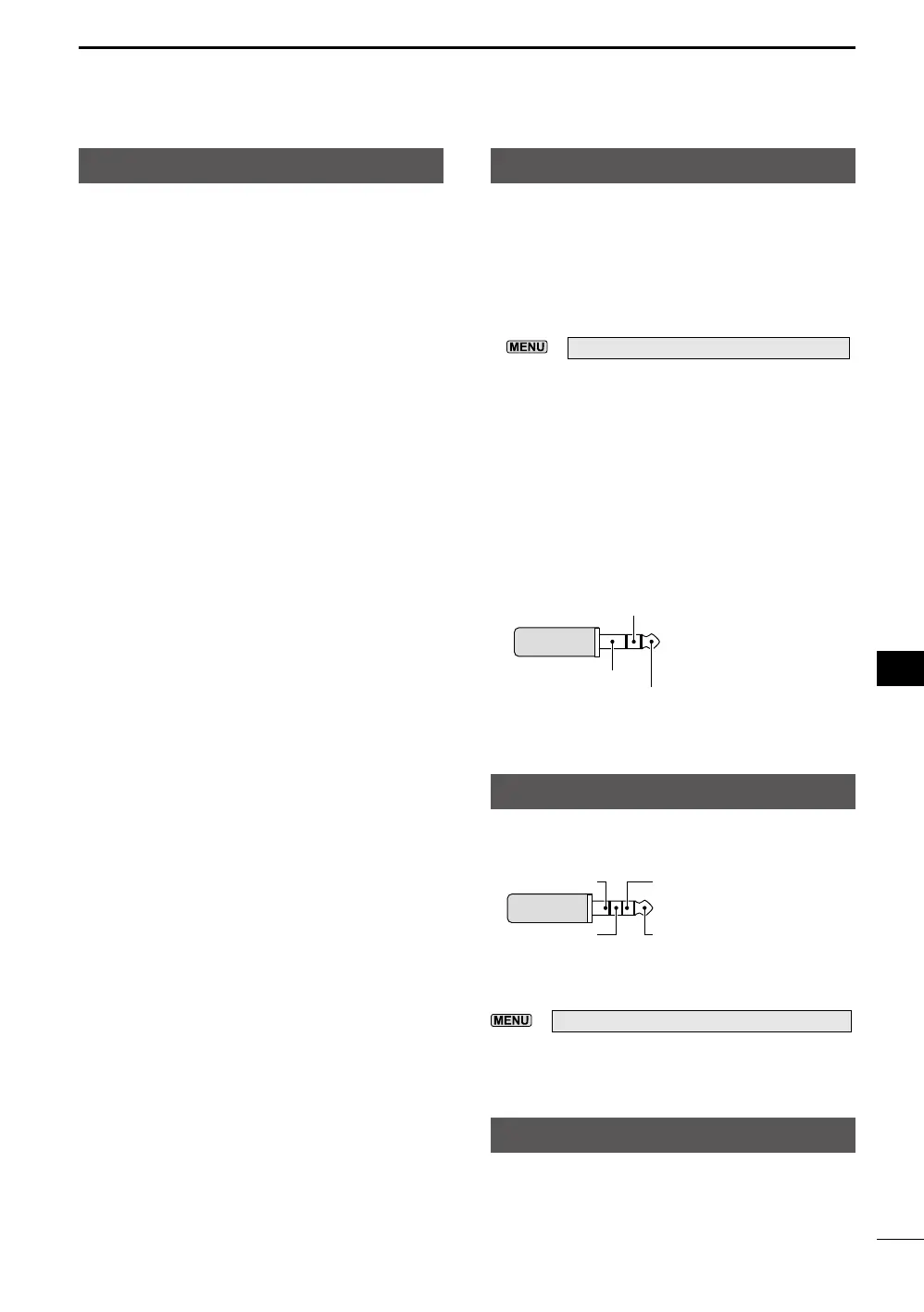
[SP]
Connect a microphone, standard stereo
headphones, or external speaker.
The output impedance and output level differ,
depending on the amplifier that is used.
LYou can change the amplifier that is used.
Set the following item according to the connected
device.
»
SET > Connectors > SP Jack Function
When using the amplifier for a speaker:
• Output impedance: 8 Ω
• Output level: More than 0.2 W
(8 Ω load, 10% distortion)
When using the amplifier for a headset:
• Output impedance: 10 Ω
• Output level: More than 5 mW
(16 Ω load, 10% distortion)
GND
Left channel
Right channel3.5 mm (1/8 inch)
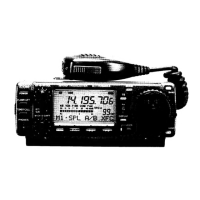
[MIC]
Connect a microphone.
2.5 mm
GND
Microphone output + PTTMicrophone key
output
+3.3 V/+8 V input*
* You can select from +3.3 V (through 470 Ω) and +8.0 V
(Maximum 10 mA)
»
SET > Connectors > MIC Jack 8V Output
LConfirm that the transceiver is OFF before
connecting or disconnecting optional equipment.