4-4
BASIC MANUAL
RECEIVING AND TRANSMITTING
4
4
Using the Digital Twin PBT
SSB, CW, RTTY, and AM modes
To reject interference, the Digital Twin Passband
Tuning (PBT) narrows the IF passband width
by electronically shifting the IF frequency to
slightly above or below the IF center frequency.
The IC-705 uses the digital function using the
FPGA (Field Programmable Gate Array) filtering
method.
LEach mode memorizes the PBT setting.
1. Push to select “PBT1.”
LEach push selects “PBT1” or “PBT2.”
2. Rotate to adjust the shift value.
• The passband width and shift value are
displayed.
LHold down
for 1 second to clear the
PBT setting.
3. Repeat steps 1 and 2 to adjust the shift
value for “PBT2.”
LInformation
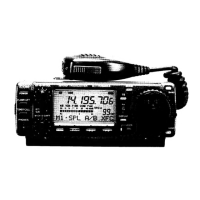
• To narrow the IF passband width, shift “PBT1” and
“PBT2” to the opposite direction from each other,
to narrow the overlapped area.
• To shift the IF left or right, set “PBT1” and “PBT2”
to the same value.
• The PBT is adjustable in 50 Hz steps in the SSB,
CW, and RTTY modes, and 200 Hz in the AM
mode. In this case, the center shift value changes
in 25 Hz steps in the SSB, CW, and RTTY modes,
and 100 Hz in the AM mode.
NOTE: While rotating , you may hear
some noise. This comes from the FPGA and
does not indicate an equipment malfunction.
LInformation
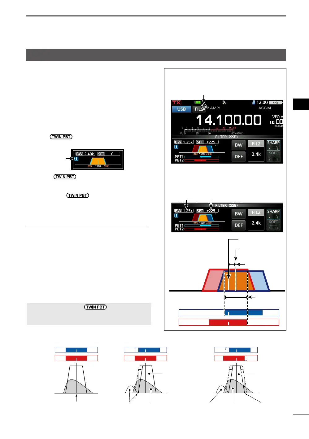
• A dot “·” is displayed on the IF Filter Indicator
when you change the IF passband width, using
the Digital Twin PBT.
• Touch the filter icon for 1 second to display the
current passband width and shift value.
Opens the FILTER screen.
PBT2
PBT2
BW:
Passband
width
SFT: Shift value
Passband center
frequency
IF center frequency
PBT is OFF
Cutting
lower passband
Cutting both higher and
lower passbands
IF center frequency Desired
signal
Interference
Passband Passband
InterferenceInterference Desired
signal
“1” (PBT1) or
“2” (PBT2)
Passband
width
Shift
value