2-4
BASIC MANUAL
PANEL DESCRIPTION
2
2
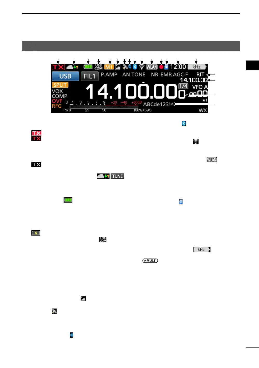
Touch screen display
1TX STATUS INDICATOR
Displays the transmit status.
• is displayed while transmitting.
•
(with a dotted line) is displayed when the
selected frequency is outside of the band edge
frequency range. (p. 3-5)
• Displayed in orange when the transceiver is in
the Terminal mode.
•
(Grayed out) is displayed when
transmission is inhibited.
2INTERNAL GATEWAY/TUNE ICON /
Displays the communication status while
using the Internal Gateway function.
Displays the antenna tuning status.
3BATTERY ICON
(p. 1-2)
Displays the charge status of the attached
battery pack.
Touch the icon to display the VOLTAGE screen.
LNo icon is displayed while using an external
power source.
L is displayed while charging the battery pack.
4USB CONNECTION INDICATOR
Displayed when an external USB device is
connected through a USB cable.
5M1~M8/T1~T8 ICONS
• “M1”~“M8” is displayed when “External
Keypad” on the CONNECTORS screen is
set to “ON,” and you are using the Memory
Keyer function.
• “T1” ~ “T8” is displayed when using the
Voice TX memory.
6PICTURE SHARE ICON
Displayed when the Share Pictures function is ON.
7GPS ICON (p. 7-1)
Displays the status of the GPS receiver.
Touch the icon to display the GPS
INFORMATION screen.
8GPS ALARM ICON
Displayed when the GPS Alarm function is ON.
9Bluetooth
®
ICON
Displayed when a Bluetooth device is
connected.
WIRELESS LAN ICON
Displays the WLAN signal strength while
connected to a wireless network.
NETWORK CONTROL ICON
Displayed while accessing the transceiver
using the optional RS-BA1, for Remote
control operation.
VOICE RECORDER ICONS z/〓
Displayed while recording or pausing using
the Voice recorder.
SD CARD ICON
(p. 6-1)
Displayed when a microSD card is inserted,
and blinks while accessing the card.
CLOCK READOUT (p. 9-1)
Displays the current local time.
Touch the readout to display both the current
local time and UTC time.
FUNCTION INDICATOR FOR MULTI-
FUNCTION CONTROL
(p. 2-8)
Displays the function that is assigned to
.
RIT/∂TX ICON
Displayed when the Receive Increment
Tuning (RIT) (p. 4-2) or ∂TX function is ON.
RIT/∂TX/SPLIT/DUPLEX FREQUENCY
READOUT
• Displays the shift offset frequency for the
RIT or ∂TX functions.
• Displays the shift frequency for the Duplex
function or the split frequency.
FREQUENCY READOUT
Displays the operating frequency.
MEMORY NAME
Displays the Memory name, if entered.
1 2 3 4 56789