3
New2001New2001
PANEL DESCRIPTION
2
New2001
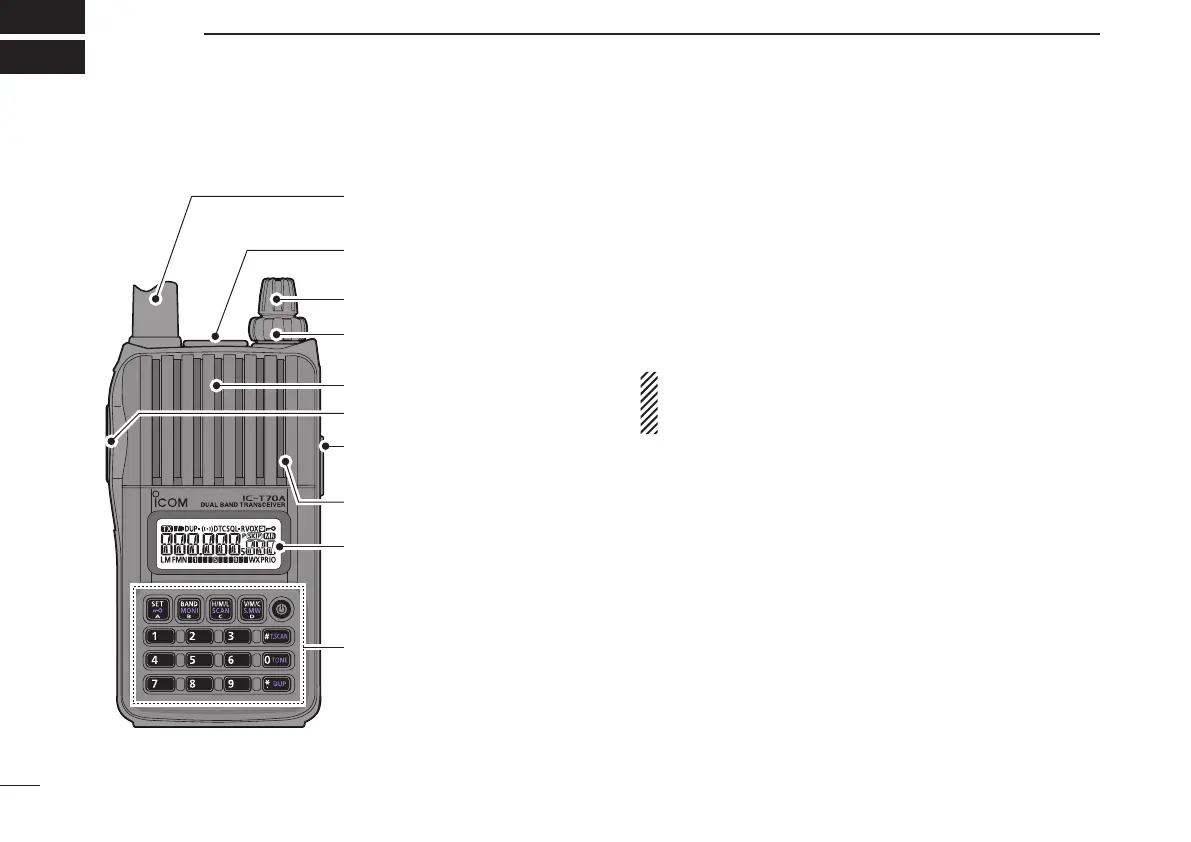
■ Front, top and side panels
Speaker
ANTENNA
CONNECTOR
EXTERNAL
DC IN JACK
VOLUME
CONTROL
CONTROL DIAL
EXTERNAL SPEAKER/
MICROPHONE JACKS
Keypad (pp. 4, 5)
Internal microphone
Function display (pp. 6, 7)
PTT SWITCH
e
r
y
w
q
t
q ANTENNA CONNECTOR (p. 2)
Connects to the supplied antenna.
•AnoptionalAD-92SMAadapter(p.79)isavailableforconnect-
ing an antenna with a BNC connector.
w EXTERNAL SPEAKER/MICROPHONE JACKS [SP/MIC]
Connect an optional speaker microphone, cloning cable,
or headset, if desired.
See page 79 for a list of available options.
Be sure to turn power OFF before connecting or dis-
connecting optional equipment to/from the [SP/MIC]
jack.
e CONTROL DIAL [DIAL]
➥ Rotate to select the operating frequency. (p. 19)
➥ During memory mode operation, rotate to select the
memory channel. (pp. 18, 30)
➥ While scanning, changes the scanning direction.
(pp. 42, 44, 45)
➥ While continuing to push [MONI](BAND), sets the
squelch level. (p. 17)
➥ After pushing [BAND] during memory mode operation,
selects the programmed bank. (p. 33)
➥ During set mode operation, rotate to select the set
items. (p. 51)