7
2
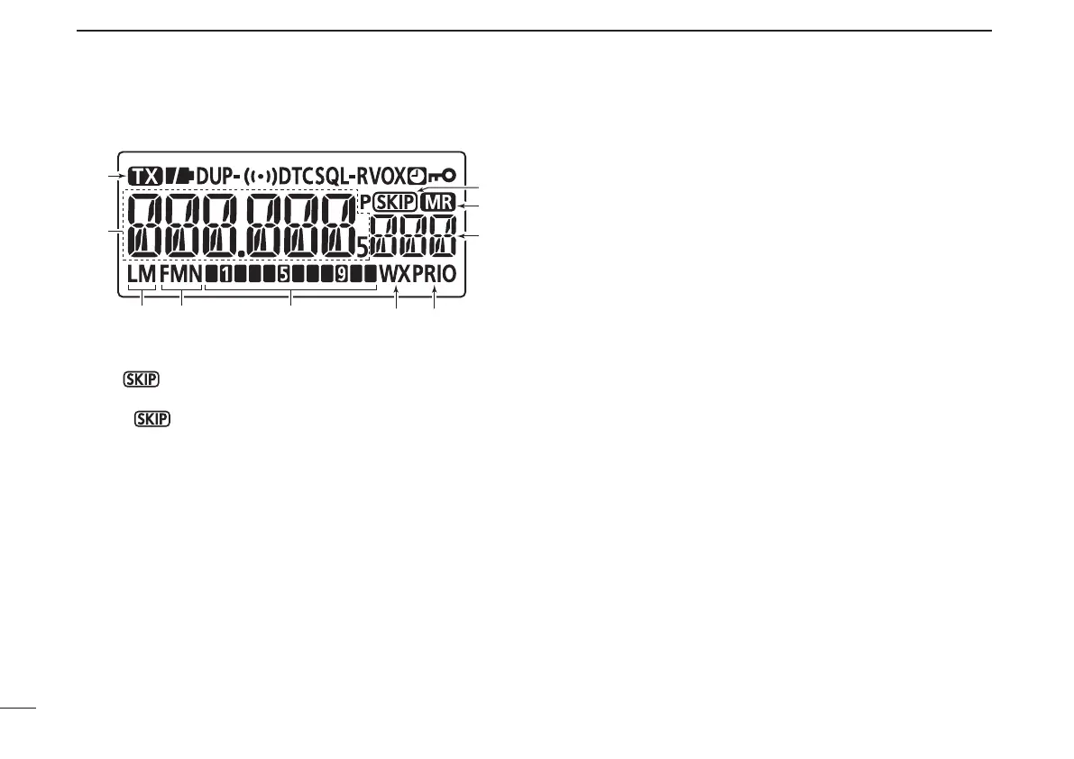
PANEL DESCRIPTION
New2001 New2001New2001
■ Function display (continued)
u SKIP ICONS
➥ “
” appears when the selected memory channel is
set as a skip channel. (p. 46)
➥ “P
” appears when the displayed frequency is set
as a skip frequency in memory mode. (p. 46)
i MEMORY ICON (pp. 18, 30)
Appears when memory mode is selected.
o MEMORY CHANNEL NUMBER
➥ Shows the selected memory channel number.
(pp. 18, 30)
➥ “C0” or “C1” appears when the call channel is selected.
(pp. 18, 29)
!0 PRIORITY WATCH ICON (pp. 49, 50)
Appears when priority watch is in use.
!1 WEATHER CHANNEL ICON (pp. 72–73)
Appears when the weather alert function is in use.
!2 S/RF METER
➥ Shows the relative signal strength while receiving sig-
nals. (p. 22)
➥ Shows the output power level while transmitting.
(pp. 22, 23)
!3 OPERATING MODE ICONS (p. 21)
Shows the selected operating mode.
•FMandFMNareselectable.
!4 POWER ICONS (p. 22)
➥ “ L” appears when low power is selected.
➥ “ M” appears when middle power is selected.
➥ No indicator appears when high power is selected.
!5 FREQUENCY READOUT
➥ Displays a variety of information, such as operating fre-
quency, set mode contents.
•Thedecimalpointblinksduringscan.
➥ During memory mode operation, the programmed
memory or memory bank name is displayed.
!6 TRANSMIT ICON (p. 23)
Appears during transmit.