3
1
PANEL DESCRIPTION
New2001 New2001
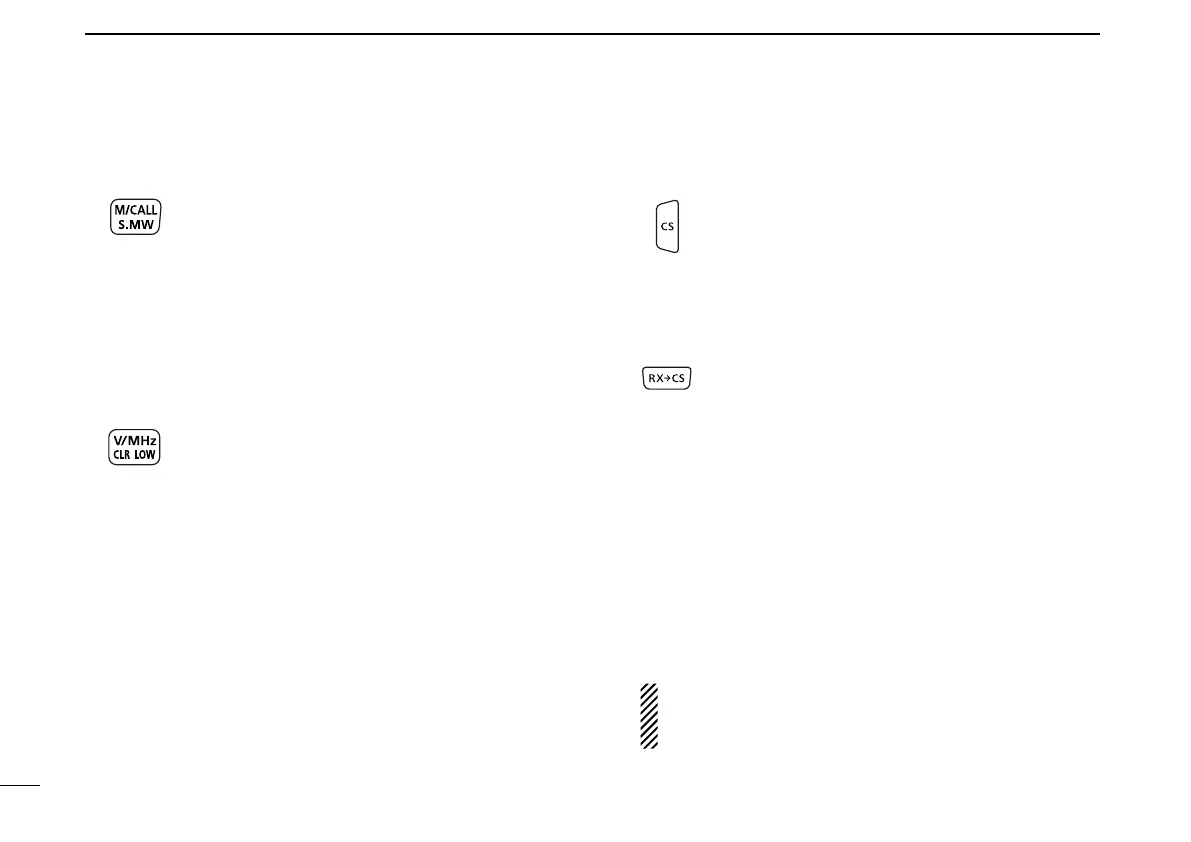
!6MEMORY/CALL•SELECTMEMORYWRITEKEY
[M/CALL•S.MW]
➥ In the VFO mode, push once to enter the Mem-
ory selection mode, push again to enter the Call
channel mode. (p. 36)
For ID-51A only
In the Call channel mode, push once to enter
the Weather channel mode.
➥ Hold down for 1 second to enter the Select
Memory Write mode. (p. 41)
!7VFO/MHz•CLEAR•OUTPUTPOWERKEY
[VFO/MHz•CLR•LOW]
➥ Push to select the VFO mode. (p. 36)
➥ While in the VFO mode, push to select
1 MHz and 10 MHz tuning steps. (p. 34)
➥With the Menu screen or Quick Menu screen
open, push to return to the operating mode be-
fore entering the menu screen.
➥ While in the Memory Name or Call Sign Pro-
gramming mode, push to delete a character. (p.
13)
➥ While scanning, push to cancel a scan.
➥ Hold down for 1 second to select the output
power. (p. 38)
•SelectthetransmitoutputpowerofHigh,Mid,Low2,
Low1 or S-low.
•Whileholdingdownthiskey,rotate[DIAL]toselect
the desired output power.
!8 CS(CALLSIGNSELECT)/D-PAD(RIGHT)KEY
[CS]/D-pad()
➥ Hold down for 1 second to enter the operating
call sign select mode.
➥ While in the DR screen, or with the Menu screen
or Quick Menuscreen open, push to select a
lower tier menu.
!9 RXÚCS(RXCALLSIGNCAPTURE)/D-PAD(UP)KEY
[RXÚCS]/D-pad()
➥ Hold down for 1 second to set the received call
signs (station and repeaters) as the operating
call signs.
•Whileholdingdownthiskey,rotate[DIAL]toselect
another call sign in RX History.
➥ While in the DR screen, or with the Menu screen
orQuickMenuscreenopen,pushtomovethe
value or option selector bar up.
@0 EXTERNALMICROPHONE/SPEAKERJACK
[MIC/SP]
Connect a cloning cable, optional speaker microphone or
headset, if desired.
See Section 18 in the Advanced instructions for a list of
available options.
Be sure to turn OFF the power before connecting or
disconnectingoptionalequipmenttoorfromthe[MIC/
SP]jack.
Front, top and side panels (Continued) ■

 Loading...


