FC6A S
ERIES
MICROS
MART
L
ADDER
P
ROGRAMMING
M
ANUAL
FC9Y-B1726 4-7
4: B
ASIC
I
NSTRUCTIONS
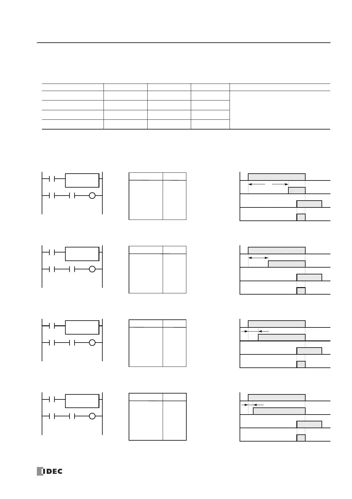
TML, TIM, TMH, and TMS (Timer)
Four types of on-delay timers are available; 1-s timer TML, 100-ms timer TIM, 10-ms timer TMH, and 1-ms timer TMS. A total of
2,000 on- and off-delay timers can be programmed in a user program. Each timer must be allocated to a unique number T0
through T1999.
For details about device ranges, see "Device Addresses" on page 2-1.
To indirectly specify the value, specify it with a data register number, and specify the value of the data register in the range of 0 to 65,535.
TML (1-s Timer)
TIM (100-ms Timer)
TMH (10-ms Timer)
TMS (1-ms Timer)
Timer Device Address Range Increments Preset Value
TML (1-s timer) T0 to T1999 0 to 65,535 s 1 s Constant: 0 to 65,535
TIM (100-ms timer) T0 to T1999 0 to 6,553.5 s 100 ms
Data registers: D0 to D7999
D10000 to D61999
TMH (10-ms timer) T0 to T1999 0 to 655.35 s 10 ms
TMS (1-ms timer) T0 to T1999 0 to 65.535 s 1 ms
I1
I0
T0
Ladder Diagram (TML)
TML
4
T0
I0
ON
OFF
T0
ON
OFF
I1
ON
OFF
Q0
ON
OFF
Timing Chart
4 s
Q0
LOD
TML
LOD
AND
OUT
I0
T0
4
I1
T0
Q0
Instruction Data
Program List
I1
I0
T1
Ladder Diagram (TIM)
TIM
20
T1
I0
ON
OFF
T1
ON
OFF
I1
ON
OFF
Q1
ON
OFF
Timing Chart
2 s
Q1
LOD
TIM
LOD
AND
OUT
I0
T1
20
I1
T1
Q1
Instruction Data
Program List
I1
I0
T2
Ladder Diagram (TMH)
TMH
100
T2
I0
ON
OFF
T2
ON
OFF
I1
ON
OFF
Q2
ON
OFF
Timing Chart
1 s
Q2
LOD
TMH
LOD
AND
OUT
I0
T2
100
I1
T2
Q2
Instruction Data
Program List
I1
I0
T3
Ladder Diagram (TMS)
TMS
500
T3
I0
ON
OFF
T3
ON
OFF
I1
ON
OFF
Q3
ON
OFF
Timing Chart
0.5 s
Q3
LOD
TMS
LOD
AND
OUT
I0
T3
500
I1
T3
Q3
Instruction Data
Program List

 Loading...