FC6A S
ERIES
MICROS
MART
L
ADDER
P
ROGRAMMING
M
ANUAL
FC9Y-B1726 7-15
7: B
INARY
A
RITHMETIC
I
NSTRUCTIONS
SUM (Sum)
Valid Devices
For valid device address ranges, see "Device Addresses" on page 2-1.
When T (timer) or C (counter) is used as S1, the timer/counter current value (TC or CC) is displayed.
When F (float) data is selected, only a data register can be designated as S1.
For source S2, 1 word is always used without regard to the data type.
When F (float) data is selected and S1 does not comply with the normal floating-point format, a user program execution error will result, turning on
special internal relay M8004 and ERR LED on the FC6A Series MICROSmart.
When S2 is 0 or exceeds the correct value range for the selected device, a user program execution error will result, turning on special internal relay
M8004 and ERR LED on the FC6A Series MICROSmart. For user program execution errors, see "User Program Execution Errors" on page 3-10.
Valid Data Types
Quantity of Source and Destination Devices
Depending on the ADD or XOR operation for W (word) and I (integer) data, the destination uses a different quantity of devices.
Calculates the total of assigned data, depending on the calculation option.
ADD:
When input is on, N blocks of 16- or 32-bit data starting at device assigned by S1 are
added together and the result is stored to the device assigned by D1. S2 specifies the
quantity of data blocks.
XOR:
When input is on, N blocks of 16-bit data starting at the device assigned by S1 are
XORed and the result is stored to the device assigned by D1. S2 specifies the quantity of
data blocks.
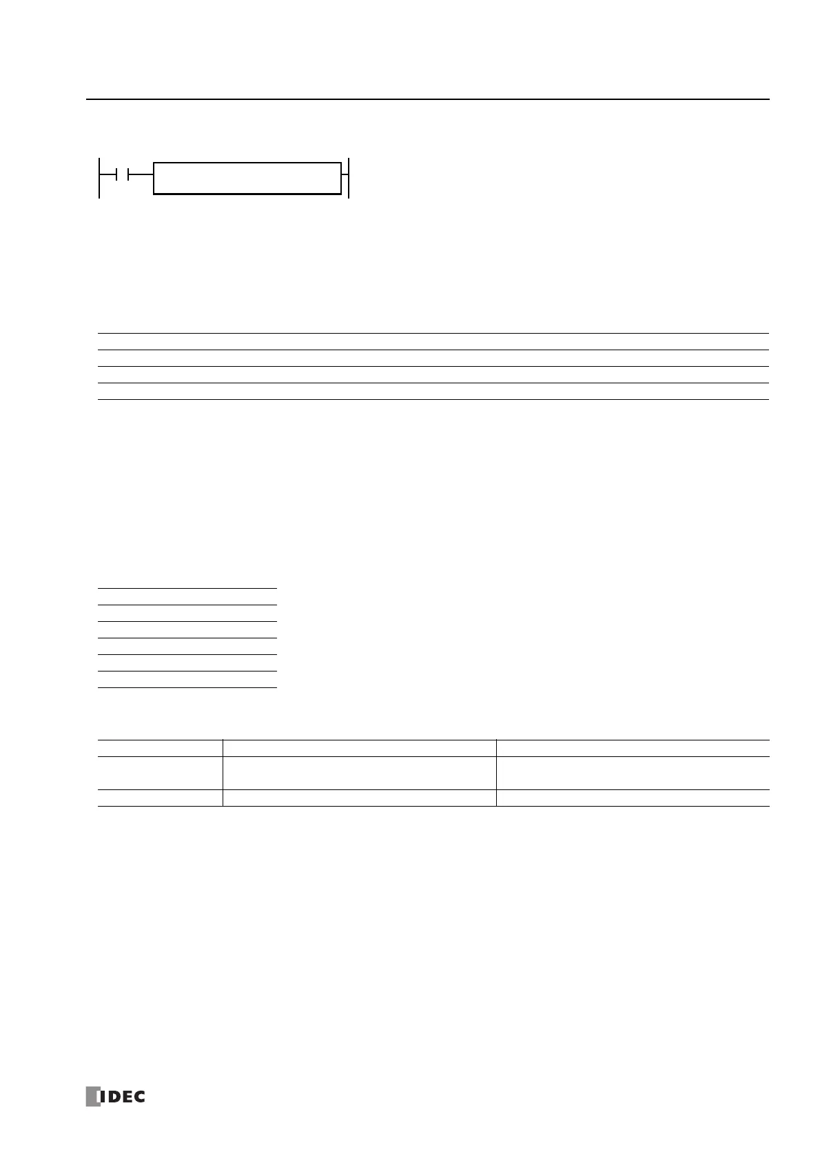
D1
*****
S1
*****
S2
*****
SUM(*)
ADD/XOR
Device Function I Q M R T C D P Constant Repeat
S1 (Source 1) First device address to calculate — — — — X X X — — —
S2 (Source 2) Quantity of data blocks ——————X — X —
D1 (Destination 1) Destination to store results — — — — — — X — — —
Calculation ADD XOR When ADD is selected, all data types can be used.
When XOR is selected, only W (word) data can be used.
When a word device such as T (timer), C (counter), or D (data register) is assigned as the source or
destination, 1 point (word or integer data) or 2 points (double-word, long, or float data) are used.
W (word) XX
I (integer) X—
D (double word) X—
L (long) X—
F (float) X—
Operation W (word), I (integer) D (double word), L (long), F (float)
ADD
S1, S2: 1 word device S1, D1: 2 word devices
D1: 2 word devices S2: 1 word device
XOR S1, S2, D1: 1 word device —

 Loading...