6: D
ATA
C
OMPARISON
I
NSTRUCTIONS
6-6 FC6A S
ERIES
MICROS
MART
L
ADDER
P
ROGRAMMING
M
ANUAL
FC9Y-B1726
ICMP>= (Interval Compare Greater Than or Equal To)
Valid Devices
For the valid device address range, see "Device Addresses" on page 2-1.
Special internal relays cannot be designated as D1.
When T (timer) or C (counter) is used as S1, S2, or S3, the timer/counter current value (TC or CC) is displayed.
When F (float) data is selected, only data register and constant can be designated as S1, S2, and S3.
When F (float) data is selected and S1, S2, or S3 does not comply with the normal floating-point format, a user program execution error will result,
turning on special internal relay M8004 and ERR LED on the FC6A Series MICROSmart.
When the data of S1 is smaller than that of S3 (S1 < S3), a user program execution error will result, turning on special internal relay M8004 and ERR
LED on the FC6A Series MICROSmart. For user program execution errors, see "User Program Execution Errors" on page 3-10.
Special Internal Relays M8150, M8151, and M8152 in ICMP>=
Three special internal relays are available to indicate the comparison result of the ICMP>= instruction. Depending on the result,
one of the three special internal relays turns on. S1 must always be greater than or equal to S3 (S1 ≥ S3).
When more than one ICMP>= or CMP= instruction is used, M8150, M8151, or M8152 indicates the result of the instruction that
was executed last.
Data type W or I: S1
≥
S2
≥
S3
→
D1 on
Data type D, L, F: S1·S1+1
≥
S2·S2+1
≥
S3·S3+1
→
D1 on
When input is on, the 16- or 32-bit data assigned by S1, S2, and S3 are
compared. When the condition is met, destination device D1 is turned on.
When the condition is not met, D1 is turned off.
ICMP>=(*) S1
*****
S2
*****
S3
*****
D1
*****
Device Function I Q M R T C D P Constant Repeat
S1 (Source 1) Data to compare XXXXXXX— X —
S2 (Source 2) Data to compare XXXXXXX— X —
S3 (Source 3) Data to compare XXXXXXX— X —
D1 (Destination 1) Comparison output — X — — — — — — —
W (word) X When a bit device such as I (input), Q (output), M (internal relay), or R (shift register) is assigned as the source,
16 points (word or integer data) or 32 points (double-word or long data) are used.
When a word device such as T (timer), C (counter), or D (data register) is assigned as the source, 1 point (word
or integer data) or 2 points (double-word, long, or float data) are used.
The destination uses only one output or internal relay regardless of the selected data type.
I (integer) X
D (double word) X
L (long) X
F (float) X
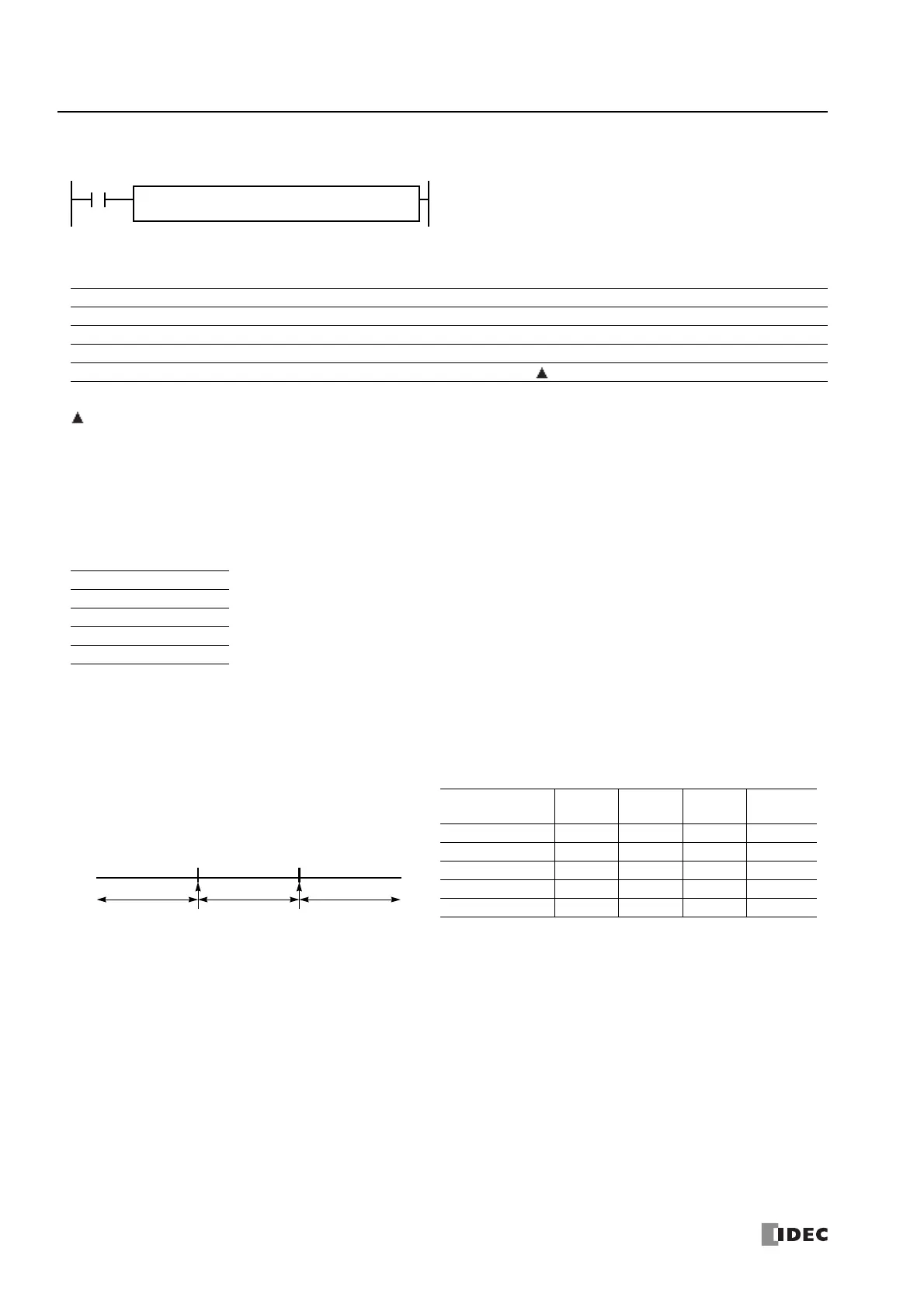
When S2 > S1, M8150 turns on.
When S2 < S3, M8151 turns on.
When S1 > S2 > S3, M8152 turns on.
S2
S3
S1
M8151 M8152 M8150
(2)(1) (3) (5)(4)
Small Large
S2 Value M8150 M8151 M8152
D1
Status
(1) S2 < S3 OFF ON OFF OFF
(2) S2 = S3 OFF OFF OFF ON
(3) S3 < S2 < S1 OFF OFF ON ON
(4) S2 = S1 OFF OFF OFF ON
(5) S2 > S1 ON OFF OFF OFF

 Loading...