3: I
NSTRUCTIONS
R
EFERENCE
3-14 FC6A S
ERIES
MICROS
MART
L
ADDER
P
ROGRAMMING
M
ANUAL
FC9Y-B1726
Values stored in the index registers is 32-bit and its data type is L (long). Index registers can directly specified as source and
destination devices in MOV(L), ADD(L), SUB(L), and MUL(L) instructions and values in index registers can be moved or
manipulated.
Notes:
• Index registers cannot be used in scripts.
• Indirect addressing to a different device type is not possible.
• Each of the following ranges of data registers is handled as a different device from the others:
All-in-One CPU module: D0 to D7999, D8000 to D8499, D10000 to D55999
Plus CPU module: D0 to D7999, D8000 to D8899, D10000 to D61999, D70000 to D269999
• If indirectly specified devices are beyond the device range, a user program execution error (1: Source/destination device exceeds range) will
occur.
• When the indirect addressing is used, the base device and index register cannot be specified with the tag names.
• Indirect addressing for data register bits is not supported.
• The four instructions that can be used to modify the values of the index registers are MOV(L), ADD(L), SUB(L), and MUL(L). Specify P (index
register) directly in those instructions.
Devices that can be indirectly addressed
Instructions supporting the indirect addressing
■ Basic Instructions
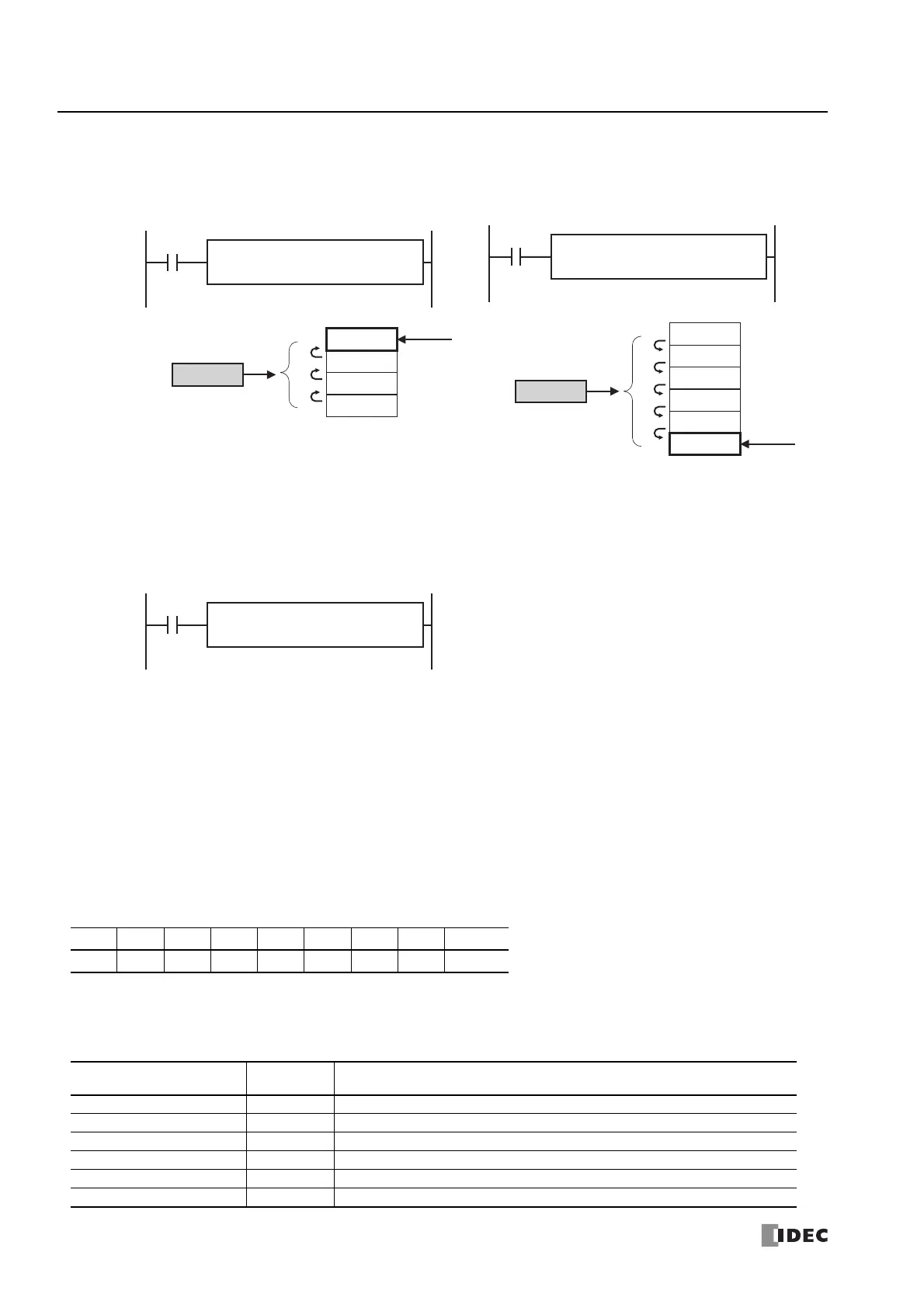
Example: MOV(D) 1234 D10:P0
•P0=-3
This indirect addressing indicates D0007, which is 3 words
behind of D0010.
•P0=5
This indirect addressing indicates D0015, which is 5 words
ahead of D0010.
Example: MOV(L) -123456 P0
• -123456 is transferred to P0.
I Q M R T C D P Constant
XXXXXXX— —
Command
Indirect
Addressing
Comments
LOD, LODN X Not possible when specifying a bit in a data register.
OUT, OUTN X Not possible when specifying a bit in a data register.
SET, RST X Not possible when specifying a bit in a data register.
AND, ANDN X Not possible when specifying a bit in a data register.
OR, ORN X Not possible when specifying a bit in a data register.
AND LOD —
1234
Transfer
REPD1 -
D0010:P0
S1 -
1234
MOV(D)
Index register
D0007
D0008
D0009
D0010
-3
3
2
1
P0
-3
D0010
D0011
D0012
D0013
D0014
D0015
+5
1
2
3
4
5
P0
5
1234
Transfer
REPD1 -
D0010:P0
S1 -
1234
MOV(D)
Index register
REPD1 -
P0
S1 -
-123456
MOV(L)

 Loading...