FC6A S
ERIES
MICROS
MART
L
ADDER
P
ROGRAMMING
M
ANUAL
FC9Y-B1726 17-1
17: AVERAGE INSTRUCTIONS
Introduction
This chapter describes the average instructions that average the specified data.
AVRG (Average)
The AVRG instruction is effective for data processing of analog input values. A maximum of 32 AVRG instructions can be programmed in a user
program.
Valid Devices
For valid device address ranges, see "Device Addresses" on page 2-1.
Special internal relays cannot be designated as D2.
When T (timer) or C (counter) is used as S1 or S3, the timer/counter current value (TC or CC) is displayed.
When F (float) data is selected, only data registers can be designated as S1 and D1.
While input is on, the AVRG instruction is executed in each scan. When the quantity of sampling cycles (scan times) designated by device S3 is 1
through 65,535, sampling data designated by device S1 is processed in each scan. When the designated sampling cycles have been completed, the
average value of the sampling data is set to the device designated by D1 (data type W or I) or D1·D1+1 (data type D, L, or F). The maximum value
of the sampling data is set to the next device, D1+1 (data type W or I) or D1+2·D1+3 (data type D, L, or F). The minimum value of the sampling
data is set to the next device, D1+2 (data type W or I) or D1+4·D1+5 (data type D, L, or F). The sampling completion output designated by device
D2 is turned on.
When the quantity of sampling cycles designated by device S3 is 0, sampling is started when the input to the AVRG instruction is turned on, and
stopped when the sampling end input designated by device S2 is turned on. Then, the average, maximum, and minimum values are set to 3 devices
starting with device designated by D1.
When the sampling exceeds 65,535 cycles, the average, maximum, and minimum values at this point are set to 3 devices starting with device
designated by D1, and sampling continues.
When the sampling end input is turned on before the sampling cycles designated by device S3 have been completed, sampling is stopped and the
results at this point are set to 3 devices starting with device designated by D1.
The average value is calculated to units, rounding the fractions of one decimal place.
When the sampling end input is not used, designate an internal relay or another valid device as a dummy for source device S2.
When F (float) data is selected and S1 does not comply with the normal floating-point format, a user program execution error will result, turning on
special internal relay M8004 and ERR LED on the FC6A Series MICROSmart. When an error occurs, incorrect S1 data are skipped. Average,
maximum, and minimum values are calculated from correct S1 data, and set to 3 devices starting with the device designated by D1. For details
about user program execution errors, see "User Program Execution Errors" on page 3-10.
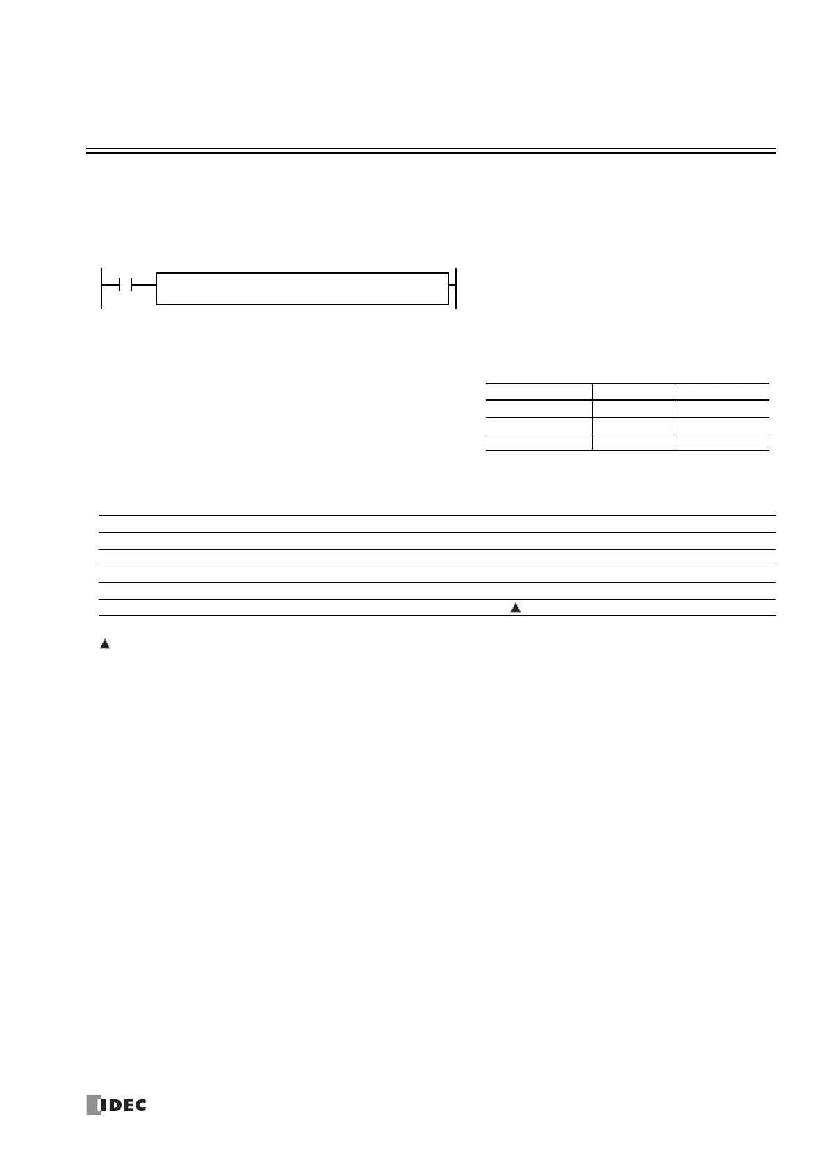
When input is on, sampling data assigned by device S1 is
processed according to sampling conditions assigned by devices
S2 and S3.
When sampling is complete, average, maximum, and minimum
values are stored to 3 consecutive devices starting with device
assigned by D1, then sampling completion output assigned by
device D2 is turned on.
AVRG(*) S1
*****
S3
*****
D1
*****
S2
*****
D2
*****
Data Type W, I D, L, F
Average D1 D1·D1+1
Maximum value D1+1 D1+2·D1+3
Minimum value D1+2 D1+4·D1+5
Device Function I Q M R T C D P Constant Repeat
S1 (Source 1) Sampling data XXXXXXX— — —
S2 (Source 2) Sampling end input X X X X — — — — — —
S3 (Source 3) Sampling cycles (scan times) XXXXXXX— 0-65,535 —
D1 (Destination 1) First device address to store results — — — — — — X — — —
D2 (Destination 2) Sampling completion output — X — — — — — — —

 Loading...