FC6A S
ERIES
MICROS
MART
L
ADDER
P
ROGRAMMING
M
ANUAL
FC9Y-B1726 15-1
15: INTERRUPT CONTROL INSTRUCTIONS
Introduction
This chapter describes interrupt control instructions that prohibit and allow user interrupt operations (interrupt input, timer
interrupt).
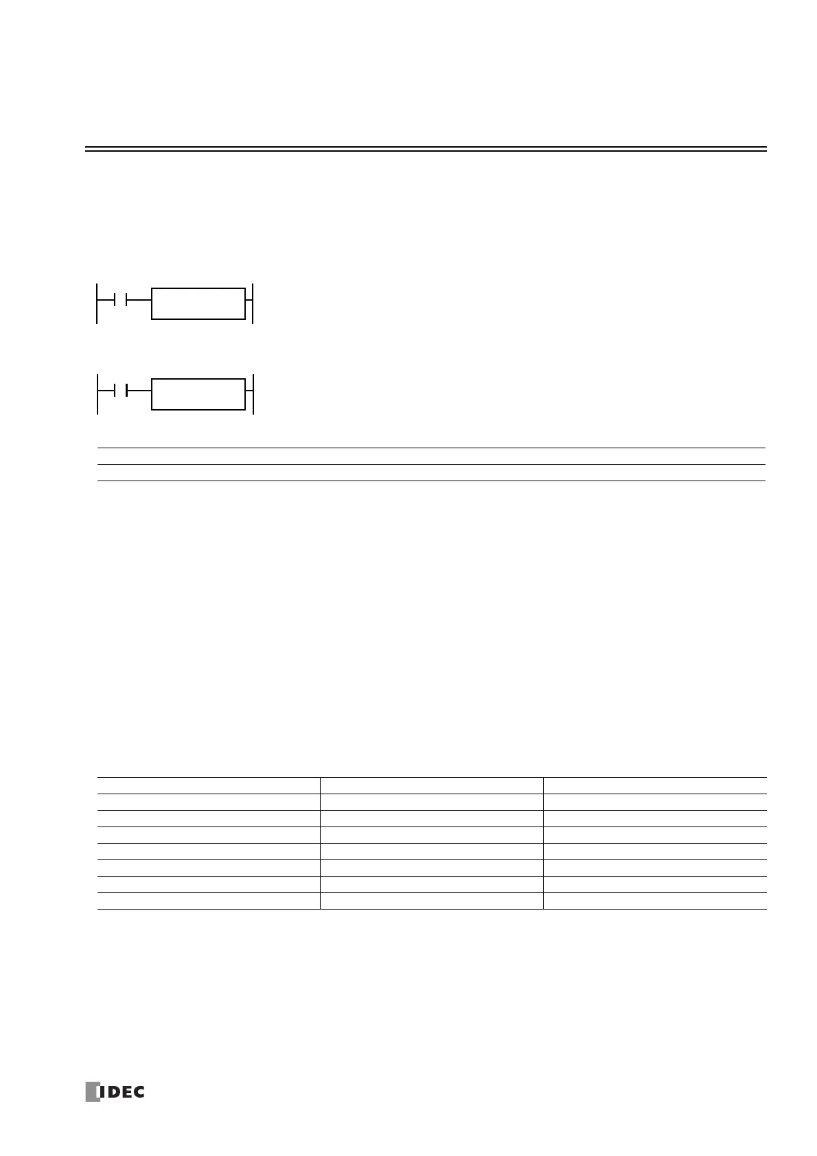
DI (Disable Interrupt)
EI (Enable Interrupt)
Valid Devices
*1 Group 1 through Group 6 or Timer Interrupt can be set.
Interrupt inputs I0 through I7 and timer interrupt selected in the Function Area Settings are normally enabled when the CPU starts. When the DI
instruction is executed, interrupt inputs and timer interrupt designated as source device S1 are disabled even if the interrupt condition is met in the
user program area subsequent to the DI instruction. When the EI instruction is executed, disabled interrupt inputs and timer interrupt designated as
source device S1 are enabled again in the user program area subsequent to the EI instruction. Different interrupts can be selected for the DI and EI
instructions to disable and enable interrupt inputs selectively. For Interrupt Input and Timer Interrupt, see Chapter 5 "Functions and Settings" -
"Interrupt Input" and "Timer Interrupt" in the "FC6A Series MICROSmart User’s Manual".
Make sure that interrupt inputs and timer interrupt designated as source device S1 are selected in the Function Area Settings. Otherwise, when the
DI or EI instruction is executed, a user program execution error will result, turning on special internal relay M8004 and the ERR LED on the FC6A
Series MICROSmart.
The DI and EI instructions cannot be used in an interrupt program. If used, a user program execution error will result, turning on special internal
relay M8004 and the ERR LED on the FC6A Series MICROSmart. For details about the user program execution errors, see "User Program Execution
Errors" on page 3-10.
Special Internal Relays M8137-M8143, M8167, and M8144: Interrupt Status
Special internal relays M8137 through M8143, M8167, and M8144 are provided to indicate whether interrupt inputs and timer
interrupt are enabled or disabled.
When input is on, interrupt inputs and timer interrupt assigned by source device S1 are disabled.
When input is on, interrupt inputs and timer interrupt assigned by source device S1 are enabled.
Device Function I Q M R T C D P Constant Repeat
S1 (Source 1) Interrupt inputs and timer interrupt — — — — — — — — X
*1
—
Interrupt Interrupt Enabled Interrupt Disabled
Group 1 (I0) M8137 ON M8137 OFF
Group 2 (I1) M8140 ON M8140 OFF
Group 3 (I3) M8141 ON M8141 OFF
Group 4 (I4) M8142 ON M8142 OFF
Group 5 (I6) M8143 ON M8143 OFF
Group 6 (I7) M8167 ON M8167 OFF
Timer Interrupt M8144 ON M8144 OFF

 Loading...