5: M
OVE
I
NSTRUCTIONS
5-14 FC6A S
ERIES
MICROS
MART
L
ADDER
P
ROGRAMMING
M
ANUAL
FC9Y-B1726
IBMVN (Indirect Bit Move Not)
Valid Devices
For valid device address ranges, see "Device Addresses" on page 2-1.
Special internal relays cannot be designated as D1.
When T (timer) or C (counter) is used as S2 or D2, the timer/counter current (TC or CC) value is displayed.
Make sure that the last source data determined by S1+S2 and the last destination data determined by D1+D2 are within the valid device range. If
the derived source or destination device exceeds the valid device range, a user program execution error will result, turning on special internal relay
M8004 and ERR LED on the FC6A Series MICROSmart. For user program execution errors, see "User Program Execution Errors" on page 3-10.
Source device S2 or destination device D2 does not have to be used. If S2 or D2 are not used, the source or destination device is determined by S1
or D1 without offset.
Examples: IBMVN
Source device S1 and destination device D1 determine the type of device. Source device S2 and destination device D2 are the offset values used to
determine the source and destination devices.
As a result, when input I0 is on, the ON/OFF status of internal relay M30 is inverted and moved to output Q12.
S1 + S2 NOT → D1 + D2
When input is on, the values contained in devices assigned by S1
and S2 are together added to determine the data source. The 1-bit
data is then inverted and moved to the destination, which is
determined by the sum of values contained in devices assigned by
D1 and D2.
IBMVN S1(R)
*****
S2
*****
D1(R)
*****
REP
**
D2
*****
Device Function I Q M R T C D P Constant Repeat
S1 (Source 1) Base address to move from X X X X — — X — 0 or 1 1-99
S2 (Source 2) Offset for S1 X X X X X X X — 0-65,535 —
D1 (Destination 1) Base address to move to — X X — — X — — 1-99
D2 (Destination 2) Offset for D1 X X X X X X X — 0-65,535 —
S1 –
M20
I0
IBMVN S2
D10
SOTU
D1 –
Q0
REPD2
C5
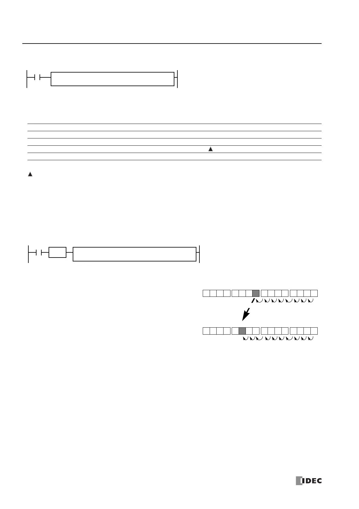
M20 + D10 NOT → Q0 + C5
If the value of data register D10 assigned by source device S2 is 8, the source
data is determined by adding the offset value to internal relay M20 assigned
by source device S1.
If the current value of counter C5 assigned by destination device D2 is 10, the
destination is determined by adding the offset value to output Q0 assigned by
destination device D1.
M37 M20M27M30
8th from M20
Q17 Q0Q7Q10
10th from Q0
Q12
NOT

 Loading...