FC6A S
ERIES
MICROS
MART
L
ADDER
P
ROGRAMMING
M
ANUAL
FC9Y-B1726 10-17
10: D
ATA
C
ONVERSION
I
NSTRUCTIONS
BCNT (Bit Count)
Valid Devices
For valid device address ranges, see "Device Addresses" on page 2-1.
Special internal relays cannot be designated as D1.
When T (timer) or C (counter) is used as S2, the timer/counter current value (TC or CC) is displayed. When T (timer) or C (counter) is used as D1,
the data is written in as a preset value (TP or CP) which can be 0 through 65,535.
The valid range of S2 (quantity of bits searched) is 1 to 256. Make sure that the search area designated by S1 plus S2 is within the valid value range.
If the source data exceeds the valid range, a user program execution error will result, turning on special internal relay M8004 and the ERR LED on
the FC6A Series MICROSmart.
When a user program execution error occurs, the execution of the instruction is canceled. The value of D1 is left unchanged and the next instruction
is executed. For user program execution errors, see "User Program Execution Errors" on page 3-10.
Since the BCNT instruction is executed in each scan while input is on, a pulse input from a SOTU or SOTD instruction should be used.
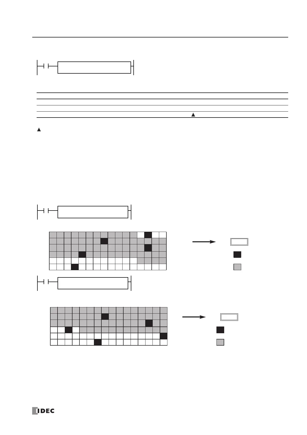
Examples: BCNT
When input is on, a search begins for the total number of bits that are on an array of
consecutive bits starting at the point assigned by source device S1. Source device S2
assigns the quantity of bits searched. The quantity of bits which are on is stored to the
destination assigned by device D1.
BCNT S1
*****
D1
*****
S2
*****
Device Function I Q M R T C D P Constant Repeat
S1 (Source 1) First bit to start search X X X X — — X — — —
S2 (Source 2) Quantity of bits searched XXXXXXX— X —
D1 (Destination 1) Destination to store quantity of ON bits — X X X X X — — —
When input is on, a search begins for the total number of bits that are on in an array
of 64 bits starting at internal relay M4 assigned by source device S1.
Since 3 bits are on in the searched area, the quantity is stored to data register D100
assigned by destination device D1.
M17 M0
M37
M20
M57
M40
M77
M60 ON
M97
M80
M117
M100 Searched area
3
D100
When input I0 is on, a search begins for the total number of bits that are on in an
array of 60 bits starting at bit 0 of data register D10 assigned by device S1.
Since 2 bits are on among the 60 bits, 2 is stored to data register D100 assigned by
device D1.
Bit 1514131211109876543210
D10
D11
D12
D13 ON
D14
D15 Searched area
2
D100

 Loading...