4: B
ASIC
I
NSTRUCTIONS
4-32 FC6A S
ERIES
MICROS
MART
L
ADDER
P
ROGRAMMING
M
ANUAL
FC9Y-B1726
END
The END instruction is always required at the end of a program; however, it is not necessary to program the END instruction after
the last programmed instruction. WindLDR automatically appends the END instruction at the end of a program.
A
scan
is the execution of all instructions from address zero to the END instruction. The time required for this execution is referred
to as one
scan time
. The scan time varies with respect to program length, which corresponds to the address where the END
instruction is found.
During the scan time, program instructions are processed sequentially. This is why the output instruction closest to the END
instruction has priority over a previous instruction for the same output. No output is initiated until all logic within a scan is
processed.
Output occurs simultaneously, and this is the first part of the END instruction execution. The second part of the END instruction
execution is to monitor all inputs, also done simultaneously. Then program instructions are ready to be processed sequentially
once again.
Ladder Diagram
I1
I2
I3
I4
I5
I6
JMP
JEND
JMP
JMP
This jump circuit will give priority to I1, I3, and I5, in that order.
When input I1 is on, the first JMP is executed so that subsequent output statuses of Q0 through Q2 are held.
When input I1 is off, the first JMP is not executed so that the following program is executed according to the actual input statuses of I2 through
I6.
When I1 is off and I3 is on, the second JMP is executed so that subsequent output statuses of Q1 and Q2 are held.
When both I1 and I3 are off, the first and second JMPs are not executed so that the following program is executed according to the actual input
statuses of I4 through I6.
Q2
Q0
Q1
LOD
JMP
LOD
OUT
LOD
JMP
LOD
OUT
LOD
JMP
LOD
OUT
JEND
I1
I2
Q0
I3
I4
Q1
I5
I6
Q2
Instruction Data
Program List
Ladder Diagram
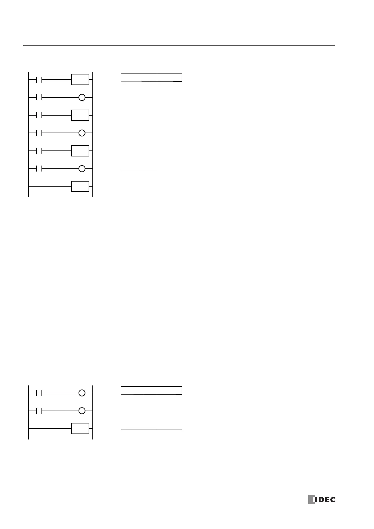
END
Q1
I0
I1
Q0
LOD
OUT
LOD
OUT
END
I0
Q0
I1
Q1
Instruction Data
Program List

 Loading...