FC6A S
ERIES
MICROS
MART
L
ADDER
P
ROGRAMMING
M
ANUAL
FC9Y-B1726 18-15
18: P
ULSE
O
UTPUT
I
NSTRUCTIONS
RAMP (Trapezoidal Control)
When the initialization input specified by S2 is turned on, the initial values configured in the WindLDR RAMP (Trapezoidal
Control) dialog box, on the Settings tab, are stored in the control registers.
The pulse control information (output on/output complete/error) is stored in the internal relays specified by D1 as the operation
status.
Notes:
• If a pulse output instruction is simultaneously executed with the same output, a user program execution error will occur.
Error code 48 will be stored in D8006 and instructions that are executed later will be canceled.
• The PULS instruction cannot be used in an interrupt program. If used in an interrupt program, a user program execution error will occur.
Error code 18 will be stored in D8006 and instruction execution will be canceled.
• If a pulse output instruction is executed with the relay output type, a user program execution error will occur.
Error code 19 is stored in D8006 and instruction execution is canceled.
• For details about the user program execution errors, see "User Program Execution Errors" on page 3-10.
Valid Devices
*1 Special data registers cannot be used.
*2 Special internal relays cannot be used. Only 0 can be specified as the first digit of the internal relay number. 1 to 7 cannot be specified.
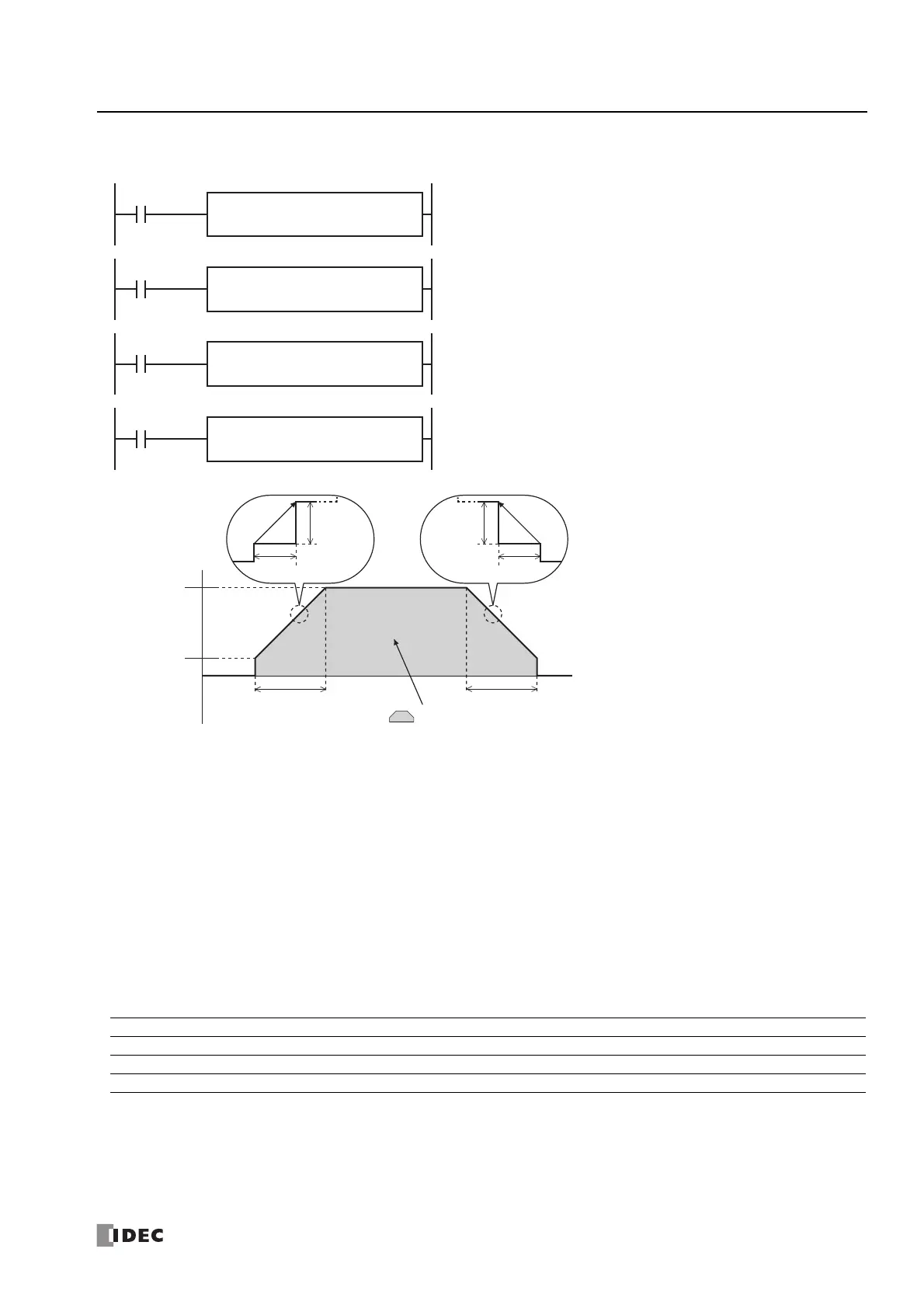
The RAMP instruction outputs pulses with a frequency change function.
When the input is on, pulses of the initial pulse frequency specified by S1 are
output, and then the pulse frequency is increased by a fixed ratio until it reaches
the steady pulse frequency.
After steady pulse output at the steady pulse frequency, the pulse frequency is
decreased before the pulse count reaches the preset value specified by S1, and
then pulse output stops when the preset value is reached.
D1
*****
S2
*****
RAMP
1
S1
*****
D1
*****
S2
*****
RAMP
2
S1
*****
D1
*****
S2
*****
RAMP
3
S1
*****
D1
*****
S2
*****
RAMP
4
S1
*****
Device Function I Q M R T C D P Constant Repeat
S1 (Source 1) Control register ——————X
*1
—— —
S2 (Source 2) Initialization input X — X — — — — — — —
D1 (Destination 1) Operation status — — X
*2
————— — —
Steady pulse
frequency
Initial pulse
frequency
Frequency
increase ratio
10 ms
area = Preset value
Frequency increase time
Frequency
decrease ratio
Frequency increase and
decrease times are the same
Frequency decrease time
10 ms
Frequency increase and
decrease ratios are the same
Frequency increase and
decrease ratios are the same
Frequency increase and
decrease ratios are the same

 Loading...