18: P
ULSE
O
UTPUT
I
NSTRUCTIONS
18-16 FC6A S
ERIES
MICROS
MART
L
ADDER
P
ROGRAMMING
M
ANUAL
FC9Y-B1726
Settings
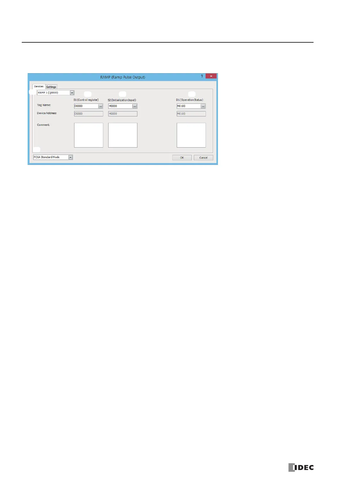
■ Devices tab
1. Select Mode
Selects the configuration mode. FC6A Standard Mode or FC5A (except FC5A-D12X1E) Compatible Mode can be
selected.
Select FC5A (except FC5A-D12X1E) Compatible Mode to use the FC5A Series MICROSmart PULS instruction specification.
When changing the PLC type from the FC5A/FC4A Series MICROSmart, FC5A (except FC5A-D12X1E) Compatible Mode is
automatically selected.
The lowest frequency that can be used with FC5A (except FC5A-D12X1E) Compatible Mode is 20 Hz
*1
.
*1 The lower limit value for the frequency that the FC5A Series MICROSmart can output is 10 Hz, but in compatibility mode this is 20 Hz.
Notes:
• The lowest frequency of pulses that can be output in FC5A (except FC5A-D12X1E) Compatible Mode is 20 Hz. A frequency lower than 20 Hz
cannot be output. If such a value is specified, the pulse frequency designation error will occur.
• The highest frequency of pulses that can be output with RAMP3 in FC5A (except FC5A-D12X1E) Compatible Mode is 5 kHz. A frequency
higher than 5 kHz cannot be output. If such a value is specified, the pulse frequency error will occur.
• FC5A compatible mode does not support the S-shaped frequency change curve.
The rest of this section is written under the assumption that FC6A Standard Mode has been selected.
Note: For details on the FC5A (except FC5A-D12X1E) Compatible Mode settings, refer to the RAMP3 instruction in Chapter 15 "Pulse Output
Instructions" in the "FC5A Series MICROSmart Pentra User's Manual Advanced Volume".
2. Select instruction
This item selects which RAMP instruction to use ("RAMP1", "RAMP2", "RAMP3" or "RAMP4").
The output and the reversible control mode and frequency that can be set differ by the instruction and CPU module type.
For limitations based on the combination of instruction, reversible control mode, and the pulse output mode, see "10. Reversible
control enable" on page 18-19.

 Loading...