FC6A S
ERIES
MICROS
MART
L
ADDER
P
ROGRAMMING
M
ANUAL
FC9Y-B1726 19-3
19: PID C
ONTROL
I
NSTRUCTION
PIDA (PID Control)
The PID instruction executes PID control and outputs the result. When auto tuning is performed, the optimal PID parameters are
calculated.
When auto/manual mode is switched, the balance-less and bumpless function automatically operates to prevent rapid changes in
the output manipulated variable.
Four alarm types, out of nine, can be set to detect process variable errors for multiple conditions.
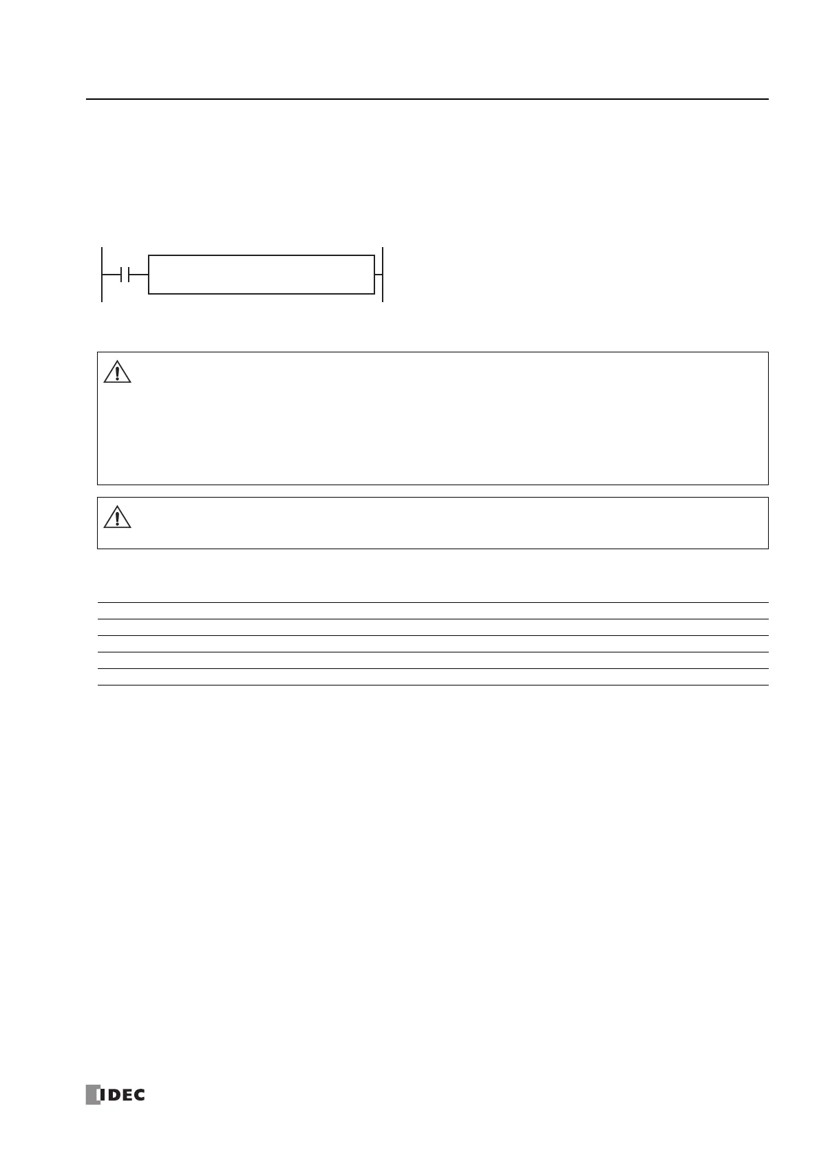
Operation
When the input is on, auto tuning and PID control are performed.
Note: The PIDA instruction and the PID instruction can be mixed in a single program, and a maximum of 32 instructions can be used.
Valid Devices
*1 Special data registers cannot be used.
*2 Special internal relays cannot be used. Only 0 can be specified as the first digit of the internal relay number. 1 to 7 cannot be specified.
S4
*****
S2
*****
PIDA S1
*****
S3
*****
• Special technical knowledge about the PID control is required to use the PIDA function of the FC6A Series MICROSmart.
Use of the PIDA function without understanding the PID control may cause the FC6A Series MICROSmart to perform
unexpected operation, resulting in disorder of the control system, damage, or accidents.
• When using the PIDA instruction for feedback control, emergency stop and interlocking circuits must be configured
outside the FC6A Series MICROSmart. If these are configured in the internal circuit and the process variable is not input
correctly, there is a risk of no longer being able to perform proper feedback control, which may damage connected
devices or cause accidents.
For PID control, see "PID Control" on page 19-23.
The PIDA instruction cannot be used in an interrupt program. If used in an interrupt program, a user program execution
error occurs, the execution of the instruction is canceled, and the next instruction is executed.
For user program execution errors, see "User Program Execution Errors" on page 3-10.
Device Function I Q M R T C D P Constant Repeat
S1 (Source 1) Control registers — — — — — — X
*1
—— —
S2 (Source 2) Initialization input X — X — — — — — — —
S3 (Source 3) Control relays — — X
*2
————— — —
S4 (Source 4) Set point ——————X
*1
—— —

 Loading...