19: PID C
ONTROL
I
NSTRUCTION
19-4 FC6A S
ERIES
MICROS
MART
L
ADDER
P
ROGRAMMING
M
ANUAL
FC9Y-B1726
Settings
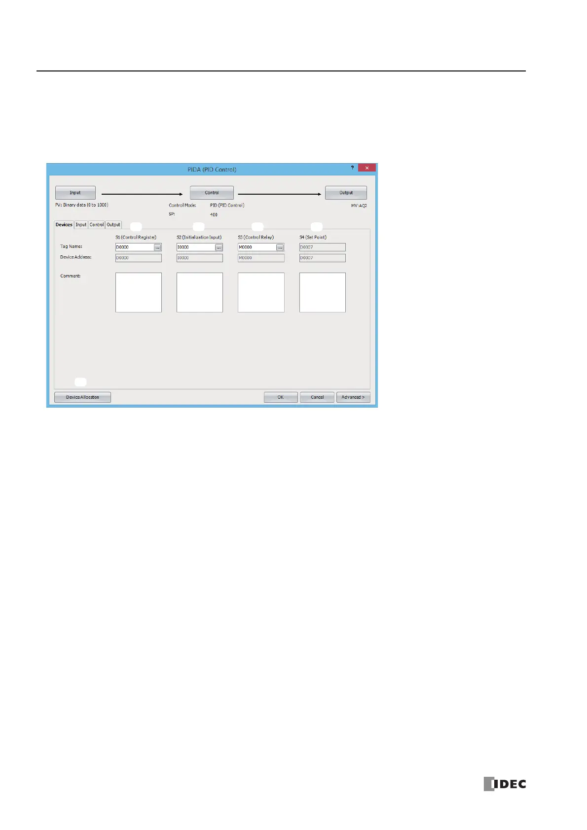
The PIDA (PID Control) dialog box contains the Devices tab, Input tab, Control tab, and Output tab.
The Devices tab configures the devices used with the PIDA instruction. The Input, Control, and Output tabs configure the
initial values of the parameters for the PIDA instruction.
■Devices tab
1. S1 (source 1): Control Register
Specify the first device to store the PIDA instruction parameters.
The devices that can be specified are data registers D0000 to D7960 and D10000 to D61960.
40 words are used starting from the specified data register.
When the initialization input is turned on, the control registers are initialized with the values set on the Input tab, the Control
tab, and the Output tab.
For initialization, see "2. S2 (source 2): Initialization Input" on page 19-4.
For the control registers, see "S1: Control Registers" on page 19-16.
2. S2 (source 2): Initialization Input
Specify the device to initialize the control registers.
The values configured on the Input tab, Control tab, and Output tab are stored in the control registers and control relays
when the initialization input turns on
*1
. An external input or an internal relay can be specified.
*1 If you want the initialization to be performed just one time, please use a SOTU (single output up) or a SOTD (single output down) instruction.
3. S3 (source 3): Control Relay
Specify the device to output control of PID control and the control results of the PIDA instruction.
16 bits are used starting from the specified device.
The devices that can be specified are internal relays M0000 to M7980 and M10000 to M21230. Special internal relays cannot be
specified.
The role of each bit is different. You can switch between auto and manual mode for the PIDA instruction and execute auto
tuning by turning the bits on and off. The PIDA instruction control result and process variable error are also output as alarms.
For tag names, device addresses, and comments, see "S3: Control Relay" on page 19-21.
4. S4 (source 4): Set Point
Shows the device that stores the PID control set point. When a data register is specified in S1 (source 1), S1+7 is automatically
allocated.
The set point (S1+7) is one data register out of the 40 words of data registers used by the control registers (1). This is
automatically displayed when a first device is specified in the control registers (1).

 Loading...