FC6A S
ERIES
MICROS
MART
L
ADDER
P
ROGRAMMING
M
ANUAL
FC9Y-B1726 5-15
5: M
OVE
I
NSTRUCTIONS
NSET (N Data Set)
Valid Devices
For valid device address ranges, see "Device Addresses" on page 2-1.
Special internal relays cannot be designated as D1.
When T (timer) or C (counter) is used as S1, the timer/counter current value (TC or CC) is displayed. When T (timer) or C (counter) is used as D1,
the data is written in as a preset value (TP or CP).
When F (float) data is selected, only data register and constant can be designated as S1, and only data register can be designated as D1.
When F (float) data is selected and S1 does not comply with the normal floating-point format, a user program execution error will result, turning on
special internal relay M8004 and ERR LED on the FC6A Series MICROSmart.
Make sure that the last destination data determined by D1+N-1 (word or integer data) or D1+2N-2 (double-word, long, or float data) is within the
valid device range. If the derived destination device exceeds the valid device range, a user program execution error will result, turning on special
internal relay M8004 and ERROR LED on the FC6A Series MICROSmart. For user program execution errors, see "User Program Execution Errors" on
page 3-10.
Valid Data Types
Example: NSET(F)
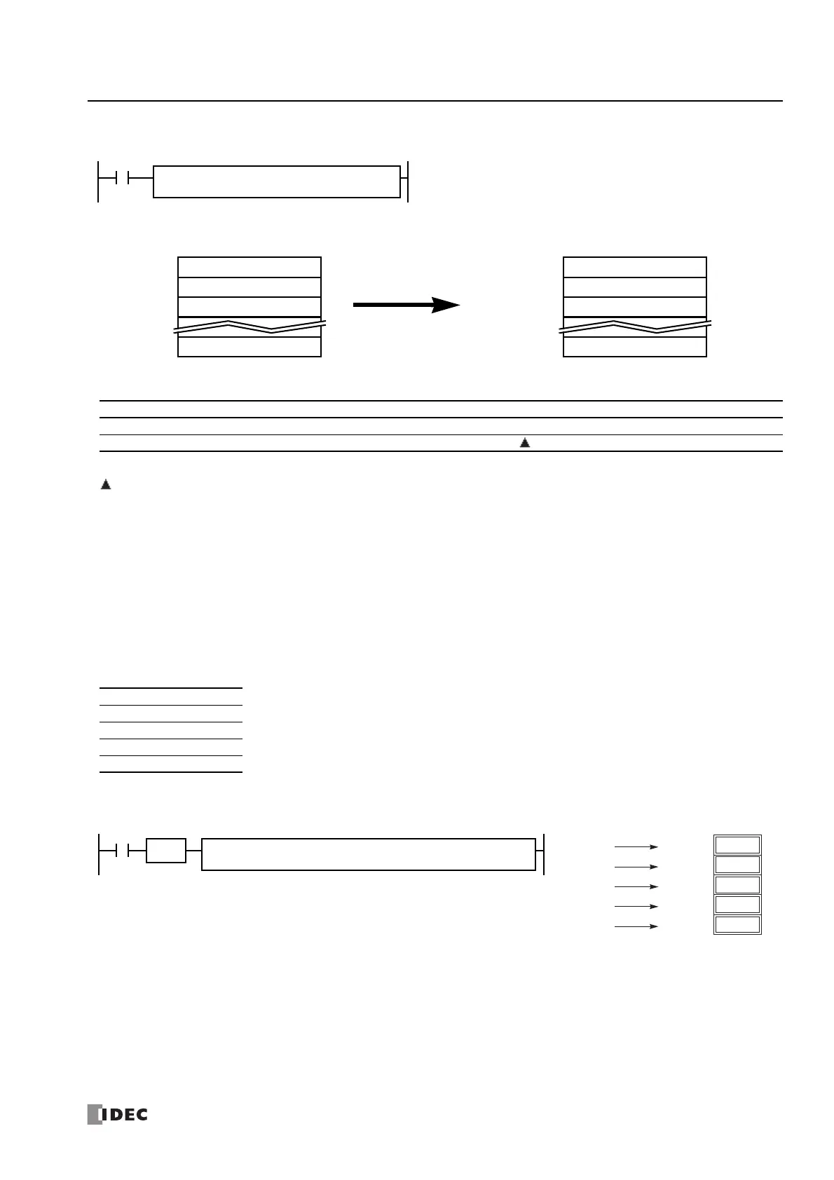
S1, S2, S3, ... , Sn → D1, D2, D3, ... , Dn
When input is on, N blocks of 16- or 32-bit data in devices assigned by S1, S2,
S3, ... , Sn are moved to N blocks of destinations, starting with device
assigned by D1.
NSET(*)
S1
*****
Sn
*****
.....
D1
*****
First 16-/32-bit dataS1
Second 16-/32-bit dataS2
Third 16-/32-bit dataS3
Nth 16-/32-bit dataSn
N blocks of 16-/32-bit data
First 16-/32-bit dataD1
Second 16-/32-bit dataD1+1 or D1+2
Third 16-/32-bit dataD1+2 or D1+4
Nth 16-/32-bit dataD1+N–1 or D1+2N–2
N blocks of 16-/32-bit data
N Data Set
Device Function I Q M R T C D P Constant Repeat
S1 (Source 1) First device address to move XXXXXXX— X —
D1 (Destination 1) First device address to move to — X X X X X — — —
W (word) X When a bit device such as I (input), Q (output), M (internal relay), or R (shift register) is assigned as the source
or destination, 16 points (word or integer data) or 32 points (double-word or long data) are used.
When a word device such as T (timer), C (counter), or D (data register) is assigned as the source or destination,
1 point (word or integer data) or 2 points (double-word, long, or float data) are used.
I (integer) X
D (double word) X
L (long) X
F (float) X
Five constants 0.51, 2.34, 7.89, 3.33, and 10.0 → D20 through D29
When input I0 is turned on, 5 constants assigned by source devices S1 through S5 are moved to 10
data registers starting with D20 assigned by destination device D1.
D1
D20
S1
0.51
S4
3.33
I0
NSET(F)
S2
2.34
S3
7.89
S5
10.0
SOTU
2.34
0.51
7.89
3.33
10.0
2.34
D22·D23
0.51
D20·D21
7.89
D24·D25
3.33
D26·D27
10.0
D28·D29

 Loading...