FC6A S
ERIES
MICROS
MART
L
ADDER
P
ROGRAMMING
M
ANUAL
FC9Y-B1726 9-3
9: S
HIFT
/ R
OTATE
I
NSTRUCTIONS
SFTR (Shift Right)
Valid Devices
For valid device address ranges, see "Device Addresses" on page 2-1.
Since the SFTR instruction is executed in each scan while input is on, a pulse input from a SOTU or SOTD instruction should be used.
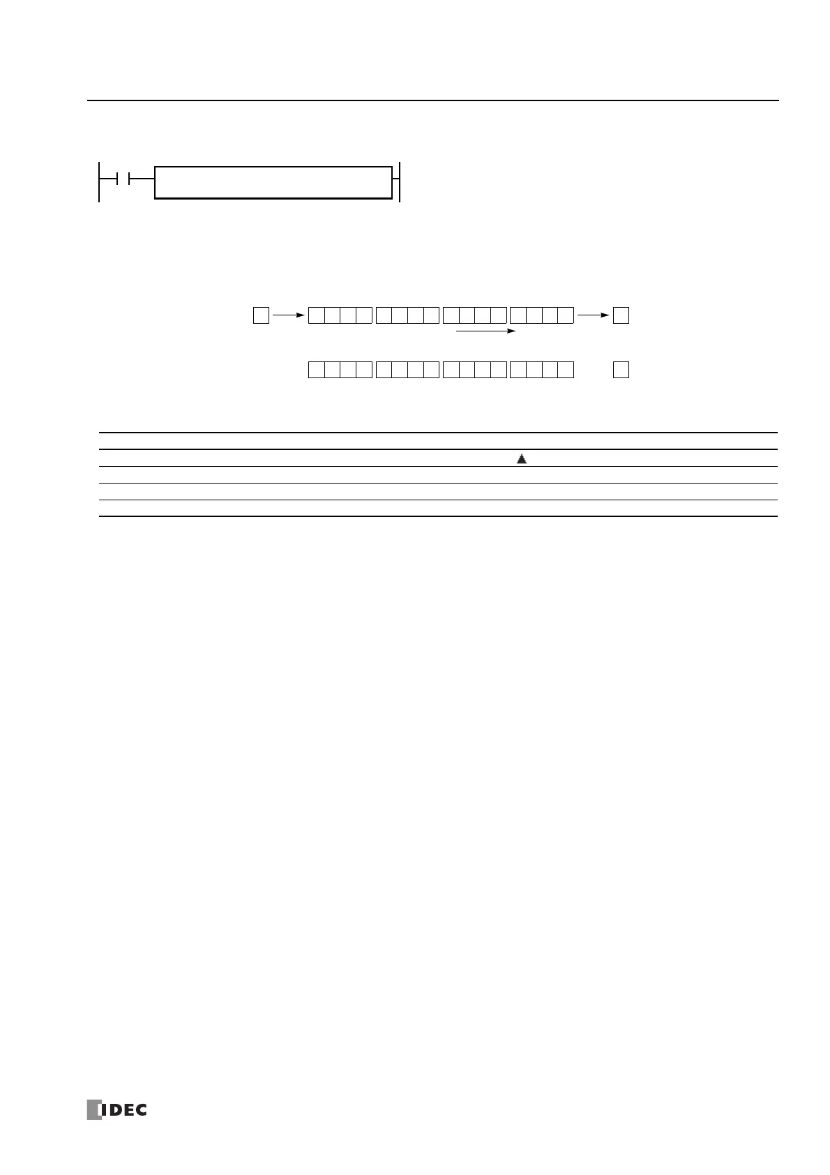
S1 → CY
When input is on, N_B-bit data string starting with source device S1 is
shifted to the right by the quantity of bits assigned by device Bits.
The result is set to source device S1, and the last bit status shifted out is set
to a carry (special internal relay M8003). Zero or 1 assigned by source
device S2 is set to the MSB.
S1
*****
Bits
**
SFTR S2
*****
N_B
*****
0Before shift: 1 0 1010 1 0 1 1 1101 0 0
CY
M8003
MSB LSB
S1
0After shift: 11 1100 0 0 1 1 0010 1 1
CY
M8003
MSB LSB
S1
Shift to the right
• S2 = 0, N_B = 16, Bits = 1
S2
Device Function I Q M R T C D P Constant Repeat
S1 (Source 1) First data for bit shift — X X — — X — — —
S2 (Source 2) Data to shift into the MSB X X X X — — — — 0 or 1 —
N_B Number of bits in the data string — — — — — — X — 1-65,535 —
Bits Quantity of bits to shift — — — — — — X — 1-15 —

 Loading...