18: P
ULSE
O
UTPUT
I
NSTRUCTIONS
18-46 FC6A S
ERIES
MICROS
MART
L
ADDER
P
ROGRAMMING
M
ANUAL
FC9Y-B1726
ARAMP (RAMP with Table)
When the initialization input specified by S2 is turned on, the initial values configured in the WindLDR ARAMP (Ramp Pulse
Output with Table) are stored in the control registers.
When the interrupt input specified by S3 is turned on, the step being executed is aborted and the interrupt step is executed.
The preset value and the steady pulse frequency for the running step are stored in the monitor registers specified by D1.
The control status including the pulse output status (output on/output direction/output complete) is stored in the operation status
specified by D2.
Notes:
• If a pulse output instruction is simultaneously executed with the same output, a user program execution error will occur.
Error code 48 will be stored in D8006 and instructions that are executed later will be canceled.
• The ARAMP instruction cannot be used in an interrupt program. If used in an interrupt program, a user program execution error will occur.
Error code 18 will be stored in D8006 and instruction execution will be canceled.
• If a pulse output instruction is executed with the relay output type, a user program execution error will occur.
Error code 19 is stored in D8006 and instruction execution is canceled.
• For details about the user program execution errors, see "User Program Execution Errors" on page 3-10.
Valid Devices
*1 Special data registers cannot be used.
*2 Special internal relays cannot be used. Only 0 can be specified as the first digit of the internal relay number. 1 to 7 cannot be specified.
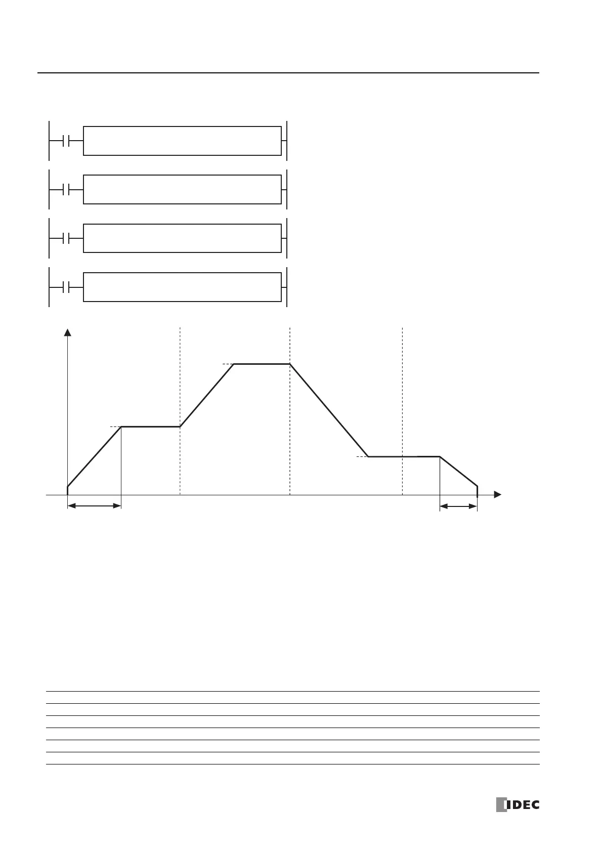
The ARAMP instructions output pulses with the frequency change
function according to the information in the frequency table.
A frequency change and target frequency are set for each step, and the
pulse frequency is controlled through the combination of these steps.
When the number of pulses that were output reaches the preset value,
the next step that is specified for each step is executed. You can
configure a maximum of 18 steps.
The pulse output operation can be selected from the following two
operations with the step option settings.
• The pulse frequency is changed at a constant rate until it reaches the
steady pulse frequency, and then a steady frequency of pulses is
output at the steady pulse frequency.
(Step 1 to 3 operations in the diagram below)
• After outputting pulses that maintain the frequency in the previous
step, the frequency is changed at a constant rate until it reaches the
steady pulse frequency.
(Step 4 operation in the diagram below)
D2
*****
D1
*****
ARAMP
1
S3
*****
S2
*****
S1
*****
D2
*****
D1
*****
ARAMP
2
S3
*****
S2
*****
S1
*****
D2
*****
D1
*****
ARAMP
3
S3
*****
S2
*****
S1
*****
D2
*****
D1
*****
ARAMP
4
S3
*****
S2
*****
S1
*****
Step 1 Step 2 Step 3
Step 4
Steady pulse
frequency
Frequency change time
Steady pulse
frequency
Steady pulse
frequency
Before
Frequency change time
Frequency
Before Before After
Time
Device Function I Q M R T C D P Constant Repeat
S1 (Source 1) Control register ——————X
*1
—— —
S2 (Source 2) Initialization input X — X — — — — — — —
S3 (Source 3) Interrupt input X — X ————— — —
D1 (Destination 1) Monitor register ——————X
*1
—— —
D2 (Destination 2) Operation status — — X
*2
————— — —

 Loading...